Troubleshooting, Chapter objectives, Fault and status leds – Rockwell Automation 1336T PLC Comm. Adapter, Series B, FRN 2.xx-3.xx User Manual
Page 227: Chapter
Chapter
8
Publication 1336 FORCE–5.13 –– September, 1998
Troubleshooting
Chapter 8 provides information to help you in trouble shooting the
PLC Communications Adapter Board. This chapter describes:
•
the fault and status LEDs
•
the fault queues
•
the fault types
•
the fault codes
!
ATTENTION: Only qualified personnel familiar with
the 1336 FORCE drive system and associated machinery
should perform troubleshooting or maintenance
functions on the drive. Failure to comply may result in
personnel injury and/or equipment damage.
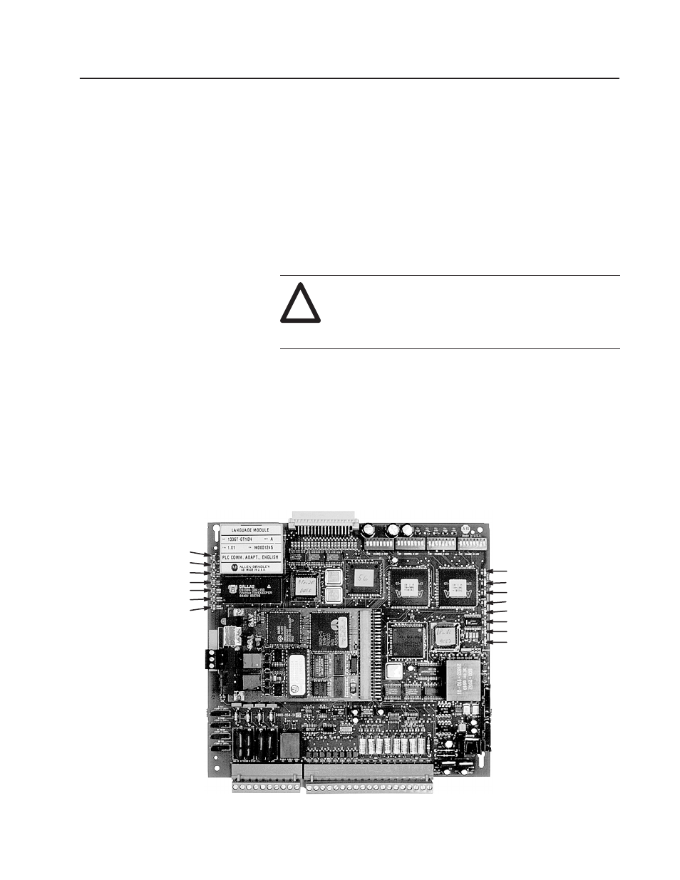
The following shows the fifteen status and fault LEDs that are
located on the PLC Communications Adapter Board to provide a
visual indication of board operation. The PLC Communications
Adapter Board is a non–serviceable device. If you did not properly
configure the PLC Communications Adapter Board, the board will
indicate faults and/or hardware malfunctions. You should verify the
system configuration before checking for faults or hardware
malfunctions.
AP Status –– D1
AP Status –– D2
Fault Out –– D4
Ext Fault –– D5
Norm Stop –– D7
Motor Thermo –– D9
Drive Enable –– D11
DP Status –– D3
DP Status –– D6
Channel A Status –– D8
Channel A Status –– D10
Channel A Status –– D12
Channel B Status –– D13
Channel B Status –– D14
Channel B Status –– D15
Chapter Objectives
Fault and Status LEDs