Rockwell Automation 1336T PLC Comm. Adapter, Series B, FRN 2.xx-3.xx User Manual
Page 41
2–13
Publication 1336 FORCE–5.13 –– September, 1998
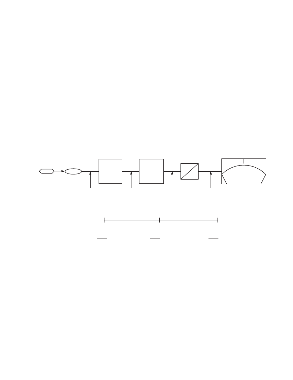
For the meter to indicate speed in both directions, you need to adjust
the scale and offset parameters as shown in Figure 2–3. Working in
the opposite direction as the analog inputs, apply the scale factor
first. The drive sends a
±
4096 digital value to indicate
±
100%
velocity feedback for a total digital range of 8192. The meter,
having an analog range of 0 through 10V
dc, requires a digital range
of 2048. This is done by applying a scale factor of 0.25 (8192
×
0.25
= 2048).
To have the 0 through 10V
dc meter indicate
±
100% feedback, you
need to apply an offset. Offset parameters for analog outputs will
again add the corresponding digital value to the range. In this case,
an offset of 5 volts adds a digital value of 1024 to the range. This
allows full range deflection on the 0 to 10 volt meter, with 5 volts
indicating zero speed.
Figure 2.3
Analog Output 1 +100% Speed Indication
–100%
Base Speed
0 Speed
+100%
Base Speed
5V
0V
10V
+4096 (+100% SPEED)
0
–4096 (–100% SPEED)
+1024
0
–1024
+2048
+1024
0
+10V = + 100% Base Speed
+5V = 0 Speed
Scale
Par 401
X 0.25
Offset
Par 400
5V = 1024
D
A
Digital Range
From Drive
Scaled by 0.25
0V = –100%
Offset by 5V, Adding 1024
Digital Value
Meter Voltage
% Base Speed
– 4096
– 1024
+ 1024
0
0 Volts
– 100%
0
0
+ 1024
0
5 Volts
0%
4096
+ 1024
+ 1024
2048
10 Volts
+ 100%
(+ 2048 = + 10V)
Par 269
Par 387
Velocity
Analog Out 1
Feedback
Filtered