Discrete plc programming – Rockwell Automation 1336T PLC Comm. Adapter, Series B, FRN 2.xx-3.xx User Manual
Page 51
3–7
Publication 1336 FORCE–5.13 –– September, 1998
Discrete PLC Programming
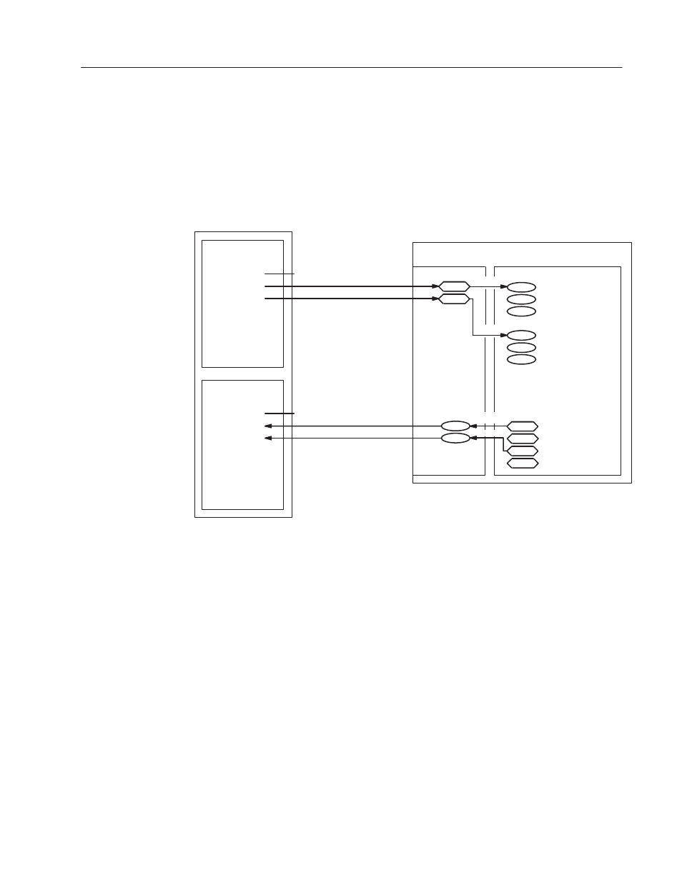
The following figure shows an application where the PLC
Communications Adapter Board has been set up for a full rack
(numbered rack 2) and the PLC controller program is using the
16–bit words for groups 1 and 2 for data transfer with the 1336
FORCE. You should refer to this figure to help understand the
following description.
162 Ext Torque Ref 1
Output Image Table
Rack 2
0:020 (Group 0)
0:021 (Group 1)
0:022 (Group 2)
0:023 (Group 3)
0:024 (Group 4)
0:025 (Group 5)
0:026 (Group 6)
0:027 (Group 7)
331
332
360
361
PLC
1336
FORCE
PLC Communications
Adapter Board
367 ChA Logic Cmd In
101 Velocity Ref 1 HI
Input Image Table
Rack 2
I:020 (Group 0)
I:021 (Group 1)
I:022 (Group 2)
I:023 (Group 3)
I:024 (Group 4)
I:025 (Group 5)
I:026 (Group 6)
I:027 (Group 7)
56 Logic Status Low
146 Velocity Feedback
Sources
Sinks
Drive Parameters
Reserved for block transfer
Reserved for block transfer
Sources
(Link)
(Link)
(Link)
(Link)
In this example, the drive has been configured so that the data
coming into source parameter 331 is linked to parameter 367, ChA
Logic Cmd In. Information linked to the 1336
FORCE using the
16–bit output word for group 1 of rack 2 must be a 16–bit word
where the bits are defined by the description of parameter 367.
Parameter 101, Velocity Ref 1 HI, has been linked to source
parameter 332. The 16–bit output word for group 2 of rack 2 must
be a 16–bit signed integer whose value is within the allowable range
of values in drive units for parameter 101.