3 setpoint inversion, 4 ramp function generator for the main setpoint, 5 s-shaped ramp – Lenze 8400 BaseLine D User Manual
Page 232: Setpoint inversion, Ramp function generator for the main setpoint, S-shaped ramp, 10 function library
10
Function library
10.2
L_NSet_1
232
Lenze · 8400 BaseLine D · Reference manual · DMS 5.5 EN · 01/2014 · TD05
_ _ _ _ _ _ _ _ _ _ _ _ _ _ _ _ _ _ _ _ _ _ _ _ _ _ _ _ _ _ _ _ _ _ _ _ _ _ _ _ _ _ _ _ _ _ _ _ _ _ _ _ _ _ _ _ _ _ _ _ _ _ _ _
10.2.3
Setpoint inversion
The output signal of the JOG function is led via an inverter.
The sign of the setpoint changes if bNSetInv is set to TRUE.
10.2.4
Ramp function generator for the main setpoint
The setpoint is now led via a ramp function generator with linear characteristic. The ramp function
generator converts setpoint step-changes at the input into a ramp.
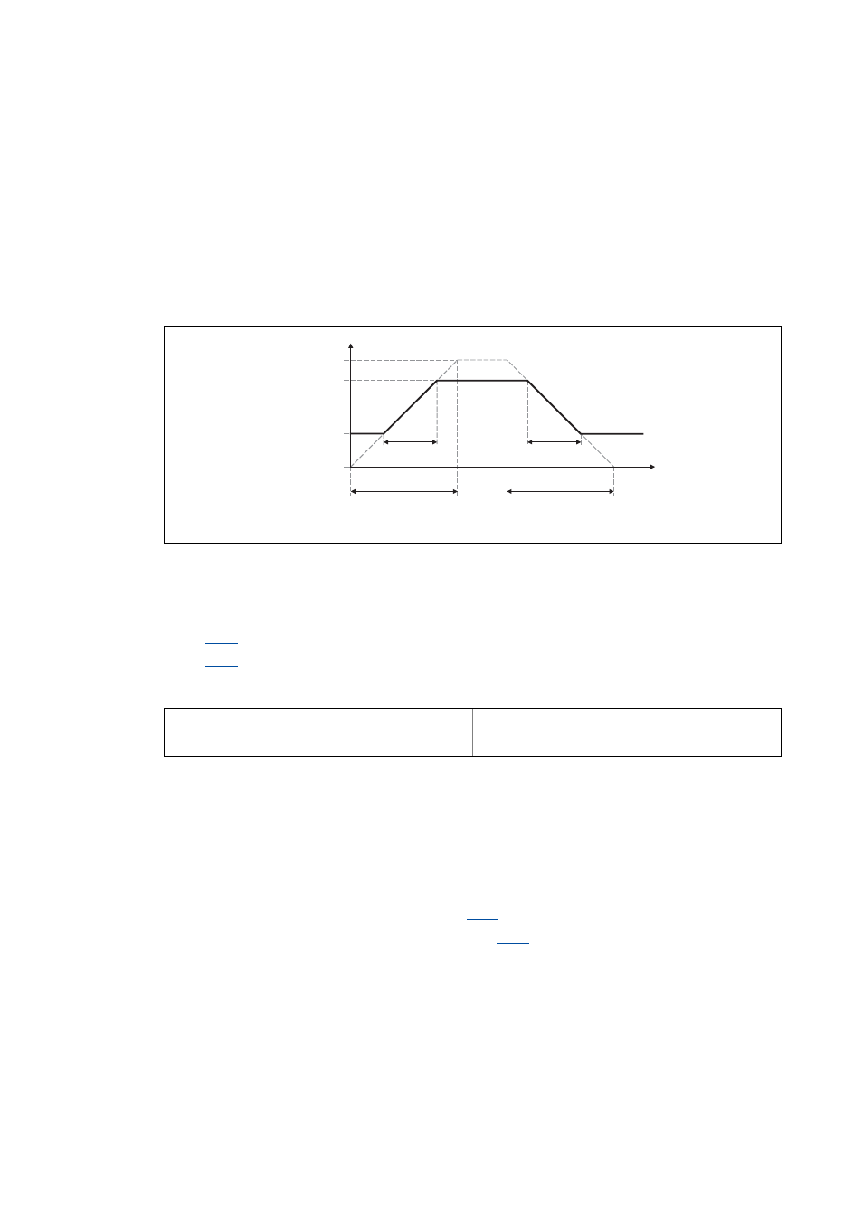
[10-3] Acceleration and deceleration times
• t
ir
and t
if
are the desired times for changing between w1 and w2.
• The ramps for acceleration and deceleration can be set individually.
•
ir
•
: Deceleration time T
if
• The t
ir
/t
if
values are converted into the required Ti times according to the following formula:
• When the bRfg0 output is set to TRUE, the ramp function generator brakes to 0 along its dece-
leration ramp.
10.2.5
S-shaped ramp
A PT1 element is connected downstream of the linear ramp function generator. This arrangement
implements an S-shaped ramp for a nearly jerk-free acceleration and deceleration.
• The PT1 element can be switched on/off via
.
• The corresponding S-ramp time can be set under
w1, w2 = change of the main setpoint as a function of t
ir
and t
if
RFG-OUT = output of the ramp function generator
RFG-OUT
100 %
w2
w1
t
0 %
t
ir
t
ir
T
ir
T
ir
T
ir
t
ir
100 %
w2 w1
–
-----------------------
⋅
=
T
if
t
if
100 %
w2 w1
–
-----------------------
⋅
=