5 terminal assignment of the control modes, Terminal assignment of the control modes, Terminal assignment of the control modes ( 137) – Lenze 8400 BaseLine D User Manual
Page 137: Terminal, Assignment of the control modes, 7d rive applica tion
7
D
rive applica
tion
7.3
Setting
param
eters (short over
view
)
Lenze ·
8400
Base
Line
D ·
Re
fe
rence m
anual
· DM
S
5.
5
EN
·
01/2014 ·
TD05
13
7
_ _
_ _
_ _
_ _
_ _
_ _
_ _
_ _
_ _
_ _
_ _
_ _
_
_ _
_ _
_ _
_ _
_ _
_ _
_ _
_ _
_ _
_ _
_ _
_ _
_ _
_ _
_ _
_ _
_ _
_ _
_ _
_
7.5
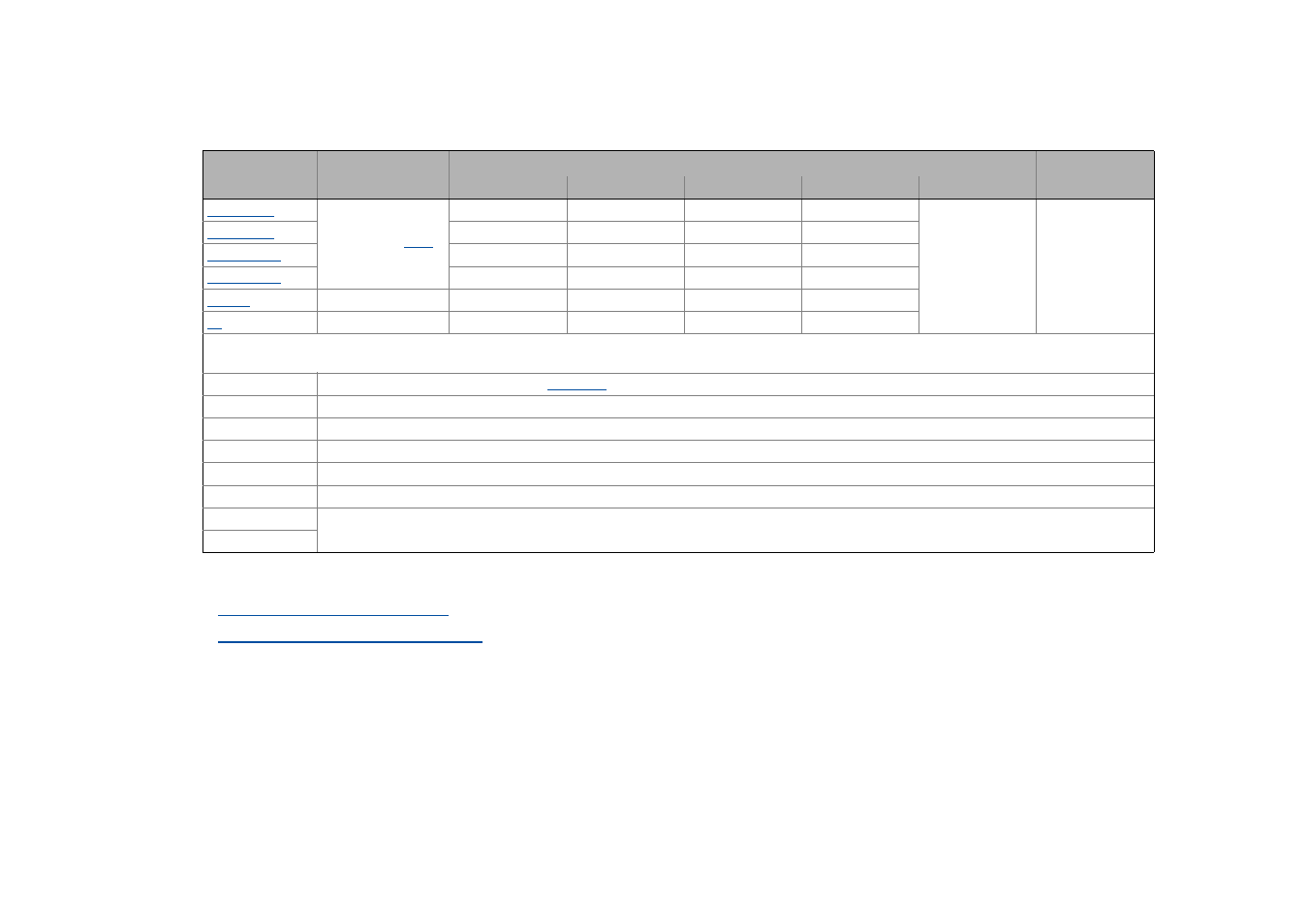
Terminal assignment of the control modes
The following table shows which functions are assigned to the digital terminals in the different control modes.
Related topics:
User-defined terminal assignment
Pre-assignment of the drive application
Analog input
Assignment of the digital terminals
Relay output
Control mode
A1U
DI1
DI2
DI3
DI4
DO1
NO / COM
Setpoint selection
10 V ≡ 100 % refe-
rence speed (
)
JOG 1/3
JOG 2/3
DCB
Cw/Ccw
Status
"Drive is ready to
start"
Status
"An error occurred"
JOG 1/3
JOG 2/3
QSP
Cw/Ccw
Cw/Ccw
DCB
MPotUp
MPotDown
JOG 1/3
JOG 2/3
Cw/QSP
Ccw/QSP
-
-
-
-
-
-
-
-
-
-
Abbreviations used:
JOG Selection of the fixed setpoints 1 ... 3 in
DCB Manual DC-injection braking
Cw/Ccw CW/CCW rotation
QSP Quick stop
MPotUp Motor potentiometer: Increase speed
MPotDown Motor potentiometer: Decrease speed
Cw/QSP Fail-safe selection of the direction of rotation in connection with quick stop
Ccw/QSP