1 parameterising analog input, Parameterising analog input, 6i/o terminals – Lenze 8400 BaseLine D User Manual
Page 113
Lenze · 8400 BaseLine D · Reference manual · DMS 5.5 EN · 01/2014 · TD05
113
6
I/O terminals
6.2
Analog terminals
_ _ _ _ _ _ _ _ _ _ _ _ _ _ _ _ _ _ _ _ _ _ _ _ _ _ _ _ _ _ _ _ _ _ _ _ _ _ _ _ _ _ _ _ _ _ _ _ _ _ _ _ _ _ _ _ _ _ _ _ _ _ _ _
6.2.1
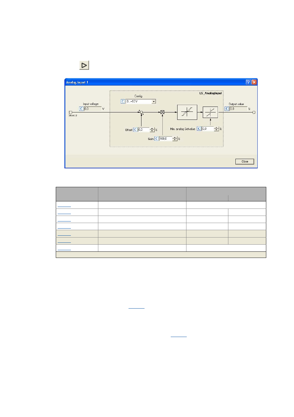
Parameterising analog input
By clicking
on the Terminal assignment tab, you reach the parameterising dialog for the analog
input:
Short overview of parameters for the analog input:
Using the analog input as current input
In the Lenze setting, a voltage signal in the range 0 ... +10 V is evaluated via the analog input termi-
nal A1U.
For evaluating a current signal:
1. Connect external 250-Ω load resistor.
2. Make the following setting in
• Selection "1: 0 ... +5 V" for 0 ... 20 mA current loop.
• Selection "2: +1 ... +5 V" for 4 ... 20 mA current loop
("life zero", with open-circuit monitoring).
3. With a configuration as 4 ... 20 mA current loop in
, set the desired error response in the
event of open circuit (Lenze setting: "Fault").
Parameter
Info
Lenze setting
Value Unit
AIN1: Config.
0: 0 ... +10 V
AIN1: Offset
0.0 %
AIN1: Gain
100.0 %
AIN1: Minimum analog setpoint
0.0 %
AIN1: Input voltage
- V
AIN1: Output value (to application)
- %
Resp. to open circuit AIN1
1: Fault
Highlighted in grey = display parameter