6 pc, 7drive application – Lenze 8400 BaseLine D User Manual
Page 141
Lenze · 8400 BaseLine D · Reference manual · DMS 5.5 EN · 01/2014 · TD05
141
7
Drive application
7.3
Setting parameters (short overview)
_ _ _ _ _ _ _ _ _ _ _ _ _ _ _ _ _ _ _ _ _ _ _ _ _ _ _ _ _ _ _ _ _ _ _ _ _ _ _ _ _ _ _ _ _ _ _ _ _ _ _ _ _ _ _ _ _ _ _ _ _ _ _ _
7.5.6
PC
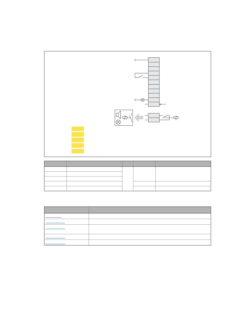
In this control mode, the control is executed via "free" parameters. The connection to inputs/out-
puts of the application takes place via the following system blocks:
Connection
Assignment
Connection
Assignment
RFR
LA_NCtrl.bFailReset
A1U
-
DI1
-
DI2
-
DI3
-
NO, COM
LA_NCtrl.bDriveFail
DI4
-
DO1
LA_NCtrl.bDriveReady
System block
Function
Any four 16-bit signals of the application can be displayed on display codes
Any four analog signals of the application can be displayed on display codes
Any eight digital signals of the application can be displayed on a bit-coded display
code
Output of 4 parameterisable analog signals
Output of 16 parameterisable digital signals
X101
NO
COM
GND
A1U
AR
RFR
DI1
DI2
DI3
DI4
24E
DO1
12I
X4
+
C472/1
C470/3
C470/4
C470/1
C470/2
Enable controller / reset error message
External supply 24 V DC
DriveFail
DriveReady
Speed setpoint
Selection of fixed setpoint 1/3
Selection of fixed setpoint 2/3
Manual DC-injection braking (DCB)
Direction of rotation CCw