2 setting the error response, Setting the error response, 8diagnostics & error management – Lenze 8400 BaseLine D User Manual
Page 150
8
Diagnostics & error management
8.5
Monitoring
150
Lenze · 8400 BaseLine D · Reference manual · DMS 5.5 EN · 01/2014 · TD05
_ _ _ _ _ _ _ _ _ _ _ _ _ _ _ _ _ _ _ _ _ _ _ _ _ _ _ _ _ _ _ _ _ _ _ _ _ _ _ _ _ _ _ _ _ _ _ _ _ _ _ _ _ _ _ _ _ _ _ _ _ _ _ _
8.5.2
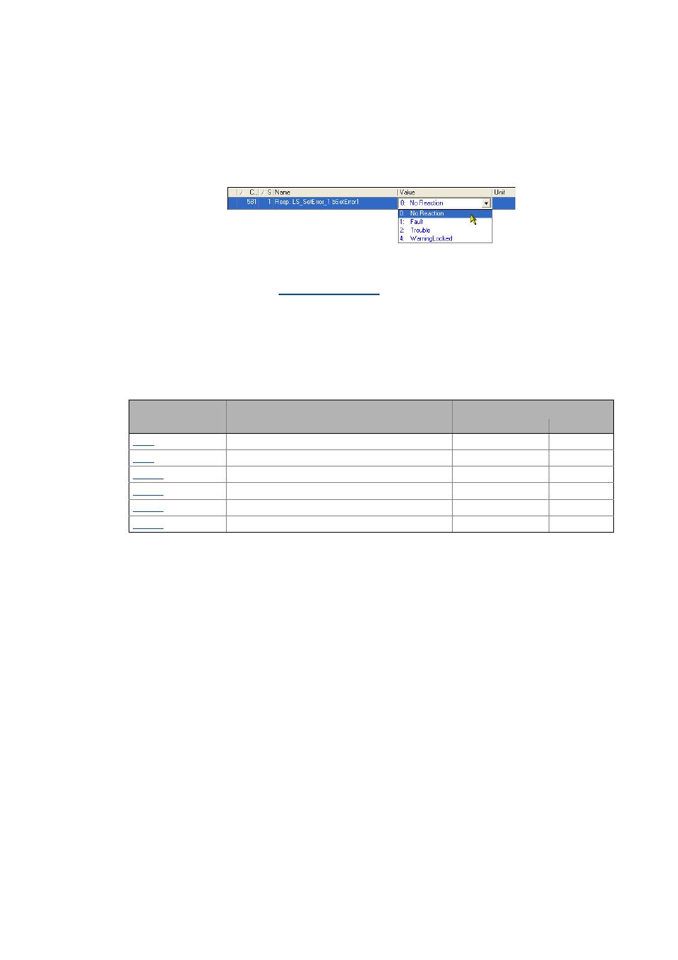
Setting the error response
When a monitoring function responds, the response set for this monitoring function (Trouble, Fault,
etc.) will be triggered.
• For many monitoring functions the response can be individually parameterised via parameters.
Tip!
The table in chapter "
" contains the error messages for which the re-
sponse can be set .
Warning thresholds
Some of the monitoring functions are activated if a defined warning threshold has been exceeded.
• The corresponding preset threshold values can be changed via the following parameters:
Parameter
Info
Lenze setting
Value Unit
Motor overload threshold (I²xt)
100 %
Device utilisat. threshold (Ixt)
100 %
Max. positive speed
120 %
Max. negative speed
120 %
Max. positive output frequency
300 Hz
Max. negative output frequency
300 Hz