6i/o terminals – Lenze 8400 BaseLine D User Manual
Page 121
Lenze · 8400 BaseLine D · Reference manual · DMS 5.5 EN · 01/2014 · TD05
121
6
I/O terminals
6.4
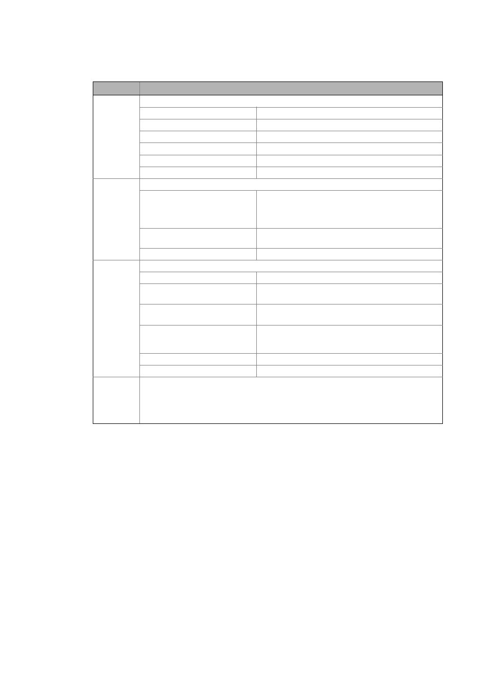
Electrical data
_ _ _ _ _ _ _ _ _ _ _ _ _ _ _ _ _ _ _ _ _ _ _ _ _ _ _ _ _ _ _ _ _ _ _ _ _ _ _ _ _ _ _ _ _ _ _ _ _ _ _ _ _ _ _ _ _ _ _ _ _ _ _ _
DI1 ... DI4
Digital inputs (according to IEC 61131-2, type 1)
LOW level: 0 ... +2.5 V
HIGH level: +10 ... +30 V
Input current: 4 mA per input (at 12 V supply of terminal 12I)
Electric strength of external voltage: ±30 V, permanent
Input impedance: 3.3 kΩ (2.0 kΩ ... 5.0 kΩ)
Processing cycle: 1 kHz (1 ms)
24E
External 24-V voltage supply
Input voltage: 24 V according to IEC 61131-2
DC 15.0 ... 30.0 V
Max. residual ripple ±5 %
SELV/PELV
Polarity reversal protection: In case of polarity reversal, the internal 12-V supply is active;
no destruction.
Current consumption: ≈ 50 mA during operation
DO1
Digital output (according to IEC 61131-2, type 1
LOW level: 0 ... +5 V
HIGH level: +15 ... +30 V
(independent of voltage at X4/24E)
Output current: max. 50 mA
(external resistance > 480 Ω at 24 V)
Electric strength of external voltage: +30 V
Integrated polarity reversal protection diode for switching
inductive loads
Processing cycle: 1 kHz (1 ms)
Behaviour in case of overload: Reduced voltage or periodical connection/disconnection
NO / COM
Relay output
• Potential-free contact (NO contact)
• AC 250 V / 3 A
• DC 24 V / 2 A ... 240 V / 0.22 A (with suppressor circuit)
Important: The minimum load must not fall below 12 V and 5 mA.
Terminal
Application / electrical data