Emergency dimmers, Emergency level, N o t e – ETC Unison Paradigm ACP Configuration Manual v2.1.2 User Manual
Page 42
37
Paradigm Architectural Control Processor Configuration Manual
Emergency Dimmers
From the Emergency Setup menu, scroll to “Emergency Dimmers” and press enter (
).
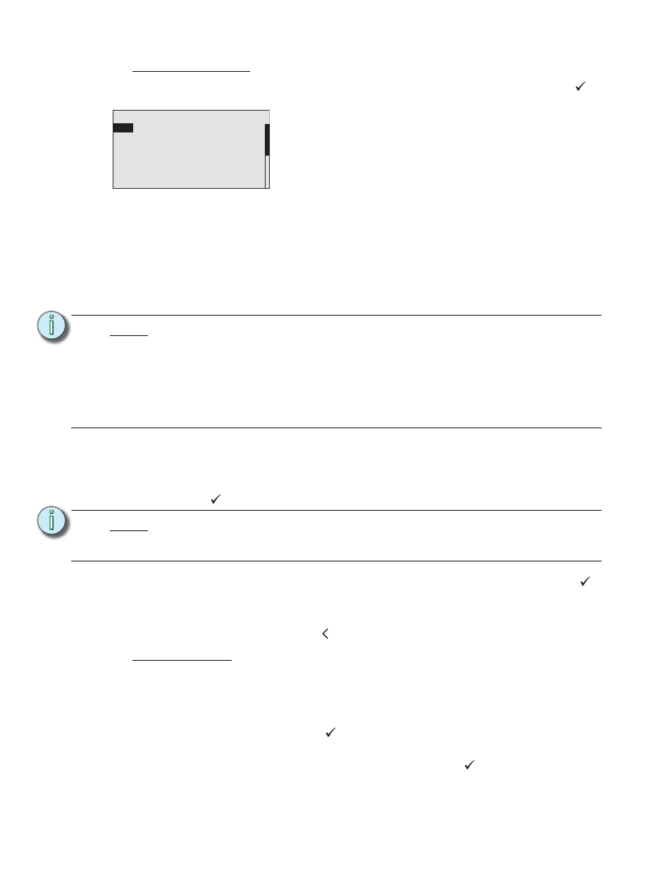
“Emergency Dimmers” displays for dimmer assignment.
Settings include:
•
“On” indicates the dimmer will turn on to the emergency preset level when the
emergency input is active.
•
“– –” indicated the dimmer is not in the emergency preset or is “Off”.
•
“NA” indicates a dimmer that is not applicable such as the CC20 or the second dimmer
for a single density module.
Step 1:
Use the touch wheel or the alpha-numeric button pad to select dimmers. You
may also use “and/thru” to specify specific or a range of dimmers. When the
dimmer selection, as seen in the title bar, is longer than the allowed 21
characters, an ellipsis “...” will display at the beginning of the title bar. Press enter
(
) to accept the selection. The focus changes to the emergency value field.
Step 2:
Use the touch wheel to set the dimmer to either “On” or “– –”. Press enter (
)
to accept the selection.
Step 3:
Continue until all dimmers are set to the desired value.
Step 4:
Press the back button ( ) to return to the Emergency Setup menu.
Emergency Level
The Emergency level is the value that the emergency circuits will activate to when the
emergency panic input is active. The emergency level defaults to 100% but can be set to a
minimum setting of 80%.
Step 5:
Within the Emergency Setup menu, use the touch wheel to scroll to “Emergency
Level” and press enter (
).
Step 6:
Use the touch wheel or alpha-numeric button pad to change the emergency level
to any value between 80% and 100%. Press enter (
) to accept the selection.
N o t e :
Modules with single density or no density, such as the D20F or CC20 modules, do
not allow edits to the second dimmer position. The second dimmer position
defaults to “NA”.
For example, if the first dimmer in the rack (slot #1) is a D20F, a single density
fluorescent dimmer module, you would notice that dimmer number 1 could be set
to be “On” or “Off” depending on your operation requirements. Dimmer number 2
would be automatically set to “NA”. In this example, setting dimmer 1 to “On” will
include both the switched and the dimmed outputs in the emergency preset.
N o t e :
Dimmer doubled dimmers are shown with both “a” and “b” dimmers. When you
have selected the dimmer number, the “a” dimmer will be selected only by default.
Use the touch wheel to scroll and select the “b” side of the dimmer.
Emergency Dimmers
1:
O n
2: O n
3: --
4: O n
5: --
6: --
7: O n
8: O n
9: O n
1 0: --
11: O n
12: O n
13: N A
14: N A 15 A : O n
15 B:O n 16 A :O n 16 B:
O n
Assign dimmers to be “On” when the panic input is active and
assign other dimmers to turn off (also known as load-shedding).