ETC Unison Paradigm Rack Mount Touchscreen User Manual
E t c, Unison paradigm touchscreen rack panel, Overview
E T C
®
I n s t a l l a t i o n G u i d e
Unison Paradigm Touchscreen Rack Panel
.
c
n
I
,
sl
o
rt
n
o
C
e
rt
a
e
h
T
ci
n
o
rt
c
el
E
4
f
o
1
e
g
a
P
le
n
a
P
k
c
a
R
n
e
e
r
c
s
h
c
u
o
T
m
gi
d
a
r
a
P
n
o
si
n
U
Corporate Headquarters 3031 Pleasant View Road, P.O. Box 620979, Middleton, Wisconsin 53562-0979 USA Tel +608 831 4116 Fax +608 836 1736
London, UK Unit 26-28, Victoria Industrial Estate, Victoria Road, London W3 6UU, UK Tel +44 (0)20 8896 1000 Fax +44 (0)20 8896 2000
Rome, IT Via Ennio Quirino Visconti, 11, 00193 Rome, Italy Tel +39 (06) 32 111 683 Fax +44 (0)20 8896 2000
Holzkirchen, DE Ohmstrasse 3, 83607 Holzkirchen, Germany Tel +49 (80 24) 47 00-0 Fax +49 (80 24) 47 00-3 00
Hong Kong Rm 1801, 18/F, Tower 1 Phase 1, Enterprise Square, 9 Sheung Yuet Road, Kowloon Bay, Kowloon, Hong Kong Tel +852 2799 1220 Fax +852 2799 9325
Service: (Americas)
(UK)
(Asia)
Web:
Copyright © 2009 ETC. All Rights Reserved. Product information and specifications subject to change.
7184M2120 Rev B Released 2009-12
ETC intends this document to be provided in its entirety.
Overview
The Unison
®
Paradigm™ Touchscreen uses a high-resolution, 7”-wide screen, color liquid-crystal
display (LCD) that is bright and easy to read, with controllable back lights. The Touchscreen is installed
in a rack panel, which is shipped separately. The Touchscreen is also available in locking cover and wall
mount configurations. The Touchscreen is powered by either LinkPower and Auxiliary power or PoE
(Power Over Ethernet 802.3af).
• Echelon
®
LinkPower
®
(LinkConnect) control network utilizing Belden 8471 (or approved equal) and 24 Vdc
Auxiliary power (two 16 AWG 1.5mm2) wires.
• PoE (Power over Ethernet 802.3af) utilizing Category 5 cable (or approved equal).
All control wiring should be installed and terminated by a qualified installer and should follow standard
wiring installation practices. Leave approximately 10 inches (254mm) of wiring in the backbox for
connection and to allow slack for future service needs. For more information about terminating Cat5
cable, refer to the ETC Ethernet Cat5 Termination Kit Setup Guide.
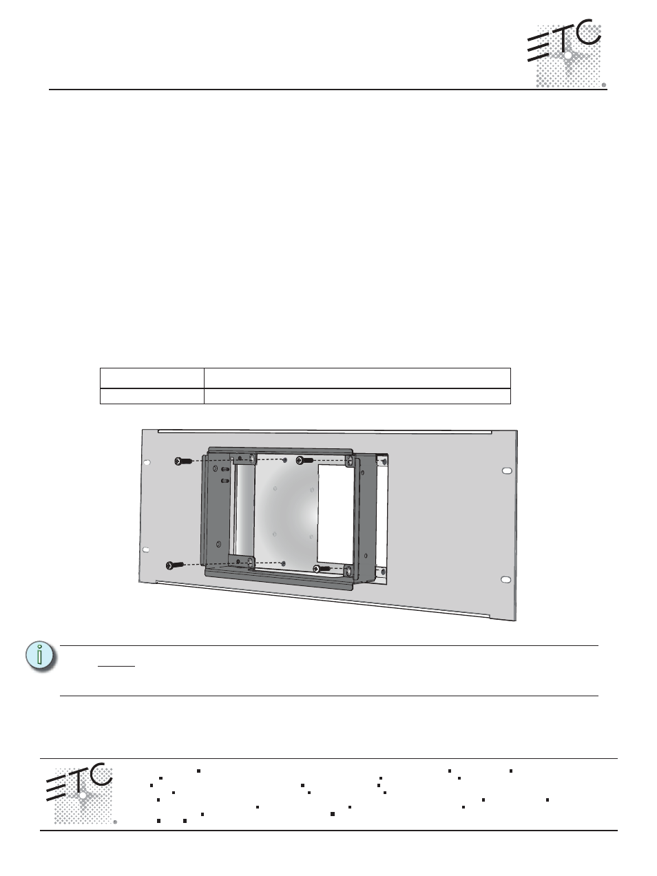
Installing the Collar
Installation should follow local codes and standard practices. Ensure that all wiring is installed correctly.
The touchscreen is supplied with an installation kit which includes the necessary hardware and
electrical supplies.
Step 1:
Slide the collar into the rack panel.
Step 2:
Install and tighten four M4 x 20mm collar mount screws through the collar into the rack
panel.
Paradigm Touchscreen Model
n
o
it
p
ir
c
s
e
D
l
e
d
o
M
P-LCD-RBB
Paradigm Touchscreen rack panel
N o t e :
It is important to orient the rack panel with the cutout on the right side to provide better
cable access between the Touchscreen and the Termination PCB. As well the collar
should be installed with the double mounting pin on the top.