ETC Unison Mosaic Rack Mount Kit and Power Supply Kit User Manual
Overview, B 2:a
Rack Mount Kit and Power Supply Kit
Installation Guide
Corporate Headquarters 3031 Pleasant View Road, P.O. Box 620979, Middleton, Wisconsin 53562-0979 USA Tel +608 831 4116 Fax +608 836 1736
London, UK Unit 26-28, Victoria Industrial Estate, Victoria Road, London W3 6UU, UK Tel +44 (0)20 8896 1000 Fax +44 (0)20 8896 2000
Rome, IT Via Pieve Torina, 48, 00156 Rome, Italy Tel +39 (06) 32 111 683 Fax +44 (0) 20 8752 8486
Holzkirchen, DE Ohmstrasse 3, 83607 Holzkirchen, Germany Tel +49 (80 24) 47 00-0 Fax +49 (80 24) 47 00-3 00
Hong Kong Rm 1801, 18/F, Tower 1 Phase 1, Enterprise Square, 9 Sheung Yuet Road, Kowloon Bay, Kowloon, Hong Kong Tel +852 2799 1220 Fax +852 2799 9325
Service: (Americas)
(UK)
(DE)
(Asia)
Web:
www.etcconnect.com
Copyright © 2010 ETC. All Rights Reserved. Product information and specifications subject to change.
7180M2130
Rev A Released 2010-12
ETC intends this document to be provided in its entirety.
Page 1 of 2
1
2:b
2:a
Overview
This installation guide illustrates the Mosaic Rack Mount kit (MSC-Rack 7180A1305) installation procedure and the installation procedure for the optional 48V Power Supply kit (MSC-PS 7180A1300).
See the reverse side for Power Supply kit details.
The Mosaic Rack Mount kit installs into a
standard 19” rack (requires 4U of rack space)
and ships with one of three front panel
designs.
Design options include:
• an opening for a Mosaic Show Control
(MSC) module
• an opening for a Mosaic MSC module
plus a Remote Device
• an opening for a Mosaic MSC module
plus two Remote Devices.
The Rack Mount kit includes the following parts:
• rack mount kit, fully assembled with din-rail and ready for MSC Controller module
(and as required Remote Device) installation.
• 8 each 10/32 x 1/2” Phillips head screws and #10 flat washers
• Cat 5 Ethernet termination kit (4101A2003 for use only as needed for building wire termination).
• 2 foot Cat5e UTP patch cable
• cable ties
• front panel of choice
A #2 Phillips (cross-head) screwdriver and a jewelers slotted screwdriver are required tools (not provided) for
installation.
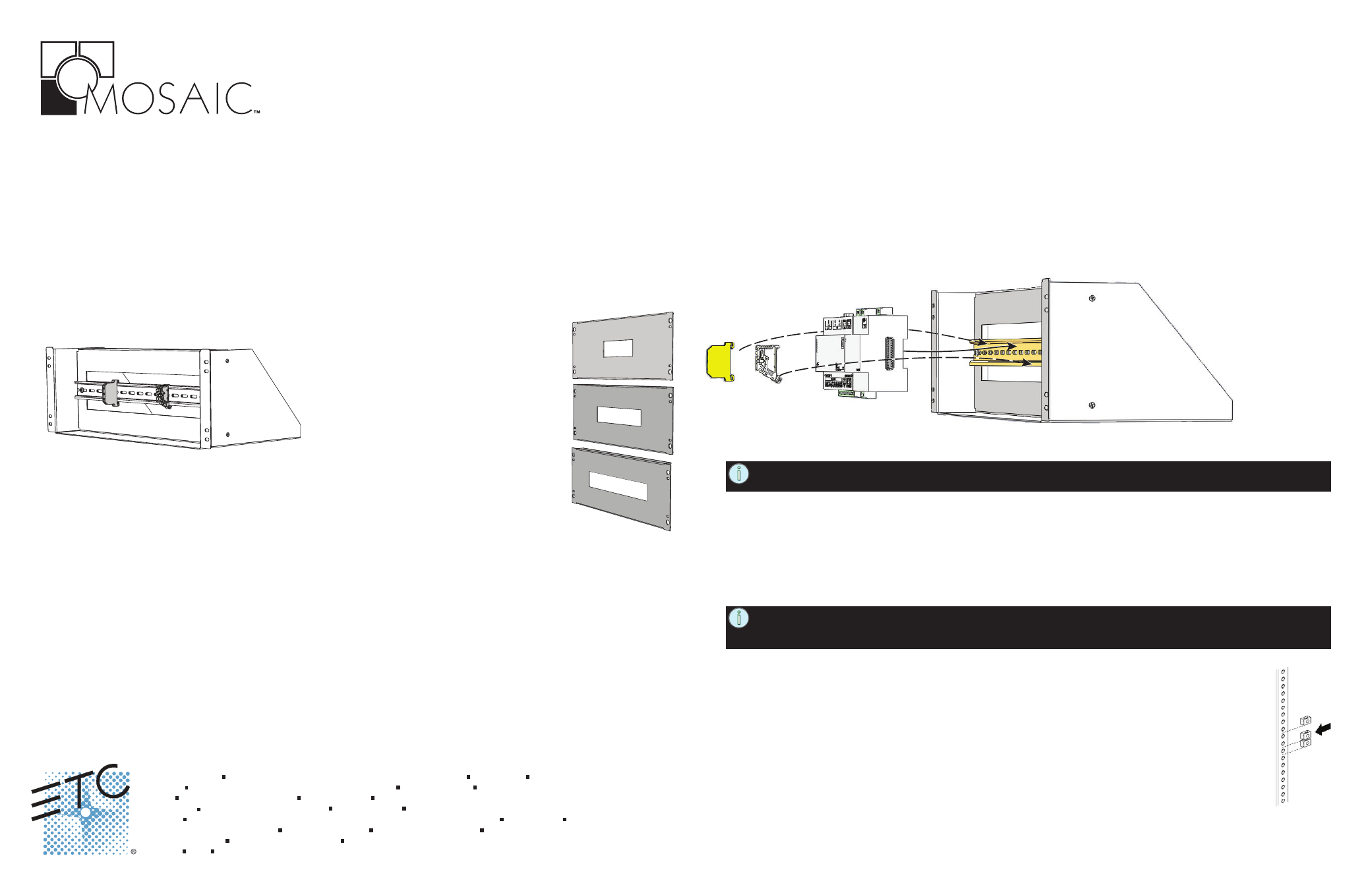
Mosaic Rack Mount Kit Features
Install Rack Mount Kit
Step 1: Snap the Mosaic Show Controller (MSC) and Remote Devices (if any) onto the din-rail. Insert the top
of the module on the rail first then swing the bottom down until it latches on the bottom rail.
NOTE: Temporarily align the face panel to the Rack Mount kit and adjust the placement of the
modules on the din-rail.
Step 2: Secure the modules in place using the din-rail ground terminal and din-rail clamp provided in the kit.
a. Snap the ground terminal onto the din-rail (left side of the Show Control module) and secure
in place using the middle screw head.
b. Snap the clamp onto the din-rail (right-side of all installed modules) and secure in place.
Step 3: Terminate the Mosaic Show Controller and Remote Devices input and outputs using the
instructions provided with the related products.
NOTE: If using Power over Ethernet to power the Mosaic Show Control module, follow the
d
e
d
i
v
o
r
p
s
i
e
l
b
a
c
5
t
a
C
t
c
e
n
n
o
C
t
e
N
A
.
d
e
d
i
v
o
r
p
t
i
k
n
o
it
a
n
i
m
r
e
t
5
t
a
C
e
h
t
n
i
s
n
o
it
c
u
r
t
s
n
i
.
e
l
u
d
o
m
l
o
r
t
n
o
C
w
o
h
S
c
i
a
s
o
M
e
h
t
d
n
a
r
o
t
c
e
n
n
o
c
5
t
a
C
e
h
t
n
e
e
w
t
e
b
n
o
it
c
e
n
n
o
c
r
o
f
Step 4: Install the entire Rack Mount kit into your 19” equipment rack.
a. If the equipment rack rails do not have threaded holes, insert the provided clip nuts
onto the rack rails in the four screw hole locations (top and bottom on each side).
b. Using four 10-32 screws and flat washers, install the rack mount kit into the
equipment rack utilizing the top and bottom mounting holes on the unit.
Step 5: Using four 10-32 screws and flat washers (provided), install the face panel to the rack unit.
If you are not utilizing Power over Ethernet (PoE) to power the Mosaic Show Controller,
reference the 48V Power Supply kit installation instructions on the
reverse side of this page.