Storage, Backup, Rack and system feedback – ETC Unison Paradigm ACP Configuration Manual v2.1.2 User Manual
Page 10: Control inputs, Left i/o, Ern left i/o board drd left i/o board
5
Paradigm Architectural Control Processor Configuration Manual
Storage
The project configuration, after upload to the Paradigm ACP, is stored in non-volatile
CompactFlash
®
memory. When the Paradigm ACP is installed in a host DRd enclosure,
dimming configuration data is also stored in the dimming engine.
Backup
The Paradigm ACP front panel features a Secure Digital (SD) media card slot and a USB
port for use of a flash drive. Use any compatible removable media to backup your
configuration files. See
for a list of compatible media.
Configuration files may include the dimming engine configuration, which is specific to a host
DRd enclosure, and the Paradigm configuration.
Additionally, an Ethernet port is provided for PC connection to the Paradigm ACP and its
connected Ethernet network. With LightDesigner open and connected to the Paradigm
ACP you can choose to retrieve and save a copy of the configuration file from the ACP to
a connected computer. Additionally, configuration updates can be uploaded from the PC to
the connected ACP.
Rack and System Feedback
The Paradigm ACP provides indicator feedback of DMX input and DMX output status,
controller power status, Ethernet status, and rack errors on LEDs visible from the front
panel of the processor with the rack door closed. Additional status information is provided
on the front panel of the Paradigm ACP display.
When the Paradigm ACP is installed in a host DRd enclosure, the default status display is
“Dimming Rack Status”. Rack status includes information pertaining to DMX addressing,
rack phase voltage, frequency settings, rack temperature and embedded dimming engine
software version number.
Clockwise rotation on the touch wheel changes the status display to “Arch Control Status”.
When the Paradigm ACP is installed in an ERn processing enclosure, this is the only status
display. “Arch Control Status” includes information pertaining to the Paradigm processor
including the processor name and IP address. In addition, the “Arch Control Status”
displays DMX port configuration, activity, host rack type and Paradigm software version
number.
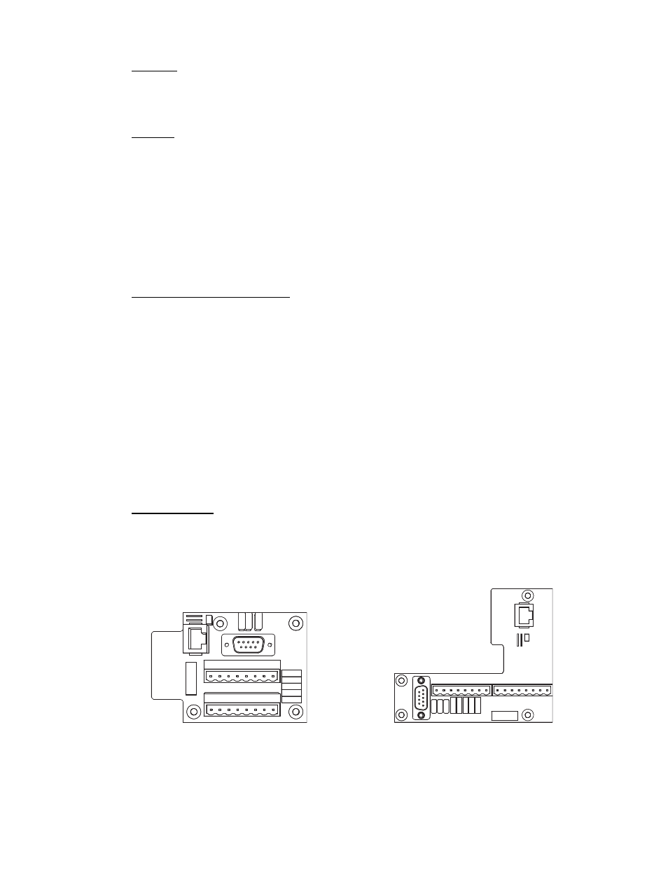
Control Inputs
Left I/O
The left I/O board on the DRd and ERn enclosures provide a selection of control inputs into
the Paradigm control network which pertain specifically to the Paradigm ACP. All
connections are pluggable for ease of installation.
•
RS-232 (serial) on a male 9 pin (D style) connector. This connection typically requires
a null modem (i.e. cross-over) cable between RS-232 sources without 3rd party signal
routing/repeating (e.g. A standard Windows
®
PC would require a null-modem cable to
interface with the left I/O board).
NO4
CO
M
4
NO3
CO
M
3
NO2
CO
M
2
NO1
CO
M
1
IN4
GND
IN3
GND
IN2
GND
IN1
GND
OUTPUTS
INPUTS
J4
J5
7183B4605 REV C
© 2012 ETC, INC.
MADE IN THE U.S.A.
RS-232
J3
J2
ETHERNET
1
6
Ethernet
RS-232
1
6
J3
J2
J4
J5
7180B5626 Rev B
IN4
GND
IN3
GND
IN2
GND
IN1
GND
INPUTS
NO4
CO
M
4
NO3
CO
M
3
NO2
CO
M
2
NO1
CO
M
1
OUTPUTS
ERn left I/O board
DRd left I/O board