ETC Unison DRd DALI Option Kit User Manual
E t c, Unison, Dali option kit installation
E T C
®
S e t u p G u i d e
Unison
®
DALI Option Kit Installation
Unison DALI Option Kit Setup Guide
Page 1 of 2
Electronic Theatre Controls, Inc.
Corporate Headquarters
3031 Pleasant View Road, P.O. Box 620979, Middleton, Wisconsin 53562-0979 USA
Tel +608 831 4116
Fax +608 836 1736
London, UK
Unit 26-28, Victoria Industrial Estate, Victoria Road, London W3 6UU, UK
Tel +44 (0)20 8896 1000
Fax +44 (0)20 8896 2000
Rome, IT
Via Pieve Torina, 48, 00156 Rome, Italy
Tel +39 (06) 32 111 683
Fax +44 (0) 20 8752 8486
Holzkirchen, DE
Ohmstrasse 3, 83607 Holzkirchen, Germany
Tel +49 (80 24) 47 00-0
Fax +49 (80 24) 47 00-3 00
Hong Kong
Rm 1801, 18/F, Tower 1 Phase 1, Enterprise Square, 9 Sheung Yuet Road, Kowloon Bay, Kowloon, Hong Kong
Tel +852 2799 1220
Fax +852 2799 9325
Service: (Americas)
(UK)
(DE)
(Asia)
Web:
Copyright © 2012 ETC. All Rights Reserved.
Product information and specifications subject to change.
7183M2210
Rev C
Released 2012-02
ETC intends this document to be provided in its entirety.
It is best to install rack options after conduit rough-in and the line, load and control terminations
are complete to reduce the likelihood of damage to the option board.
DALI Option Kit
Overview
The Digital Addressable Lighting Interface option kit (DRd-DALI) controls 24 loops of 64 DALI
compatible fluorescent ballasts in a broadcast mode. Each of the 24 DALI loops are linked one
to one with a rack circuit for power control. For example, DALI loop 1 is controlled by DRd rack
dimmer 1, DALI loop 2 is controlled by DRd rack dimmer 2, etc.
To control DALI fluorescent ballasts, the rack circuit must be populated with a dimmer or relay
module and assigned to DALI dimmer mode within the ACP software. Reference the related
architectural control processor programming guide for instruction to change dimmer mode.
The DALI option kit is limited to 64 DALI compatible fluorescent ballasts per DALI loop. All DALI
fluorescent ballasts connected to that loop will respond at the same time and to the same level
as sent by the broadcast command.
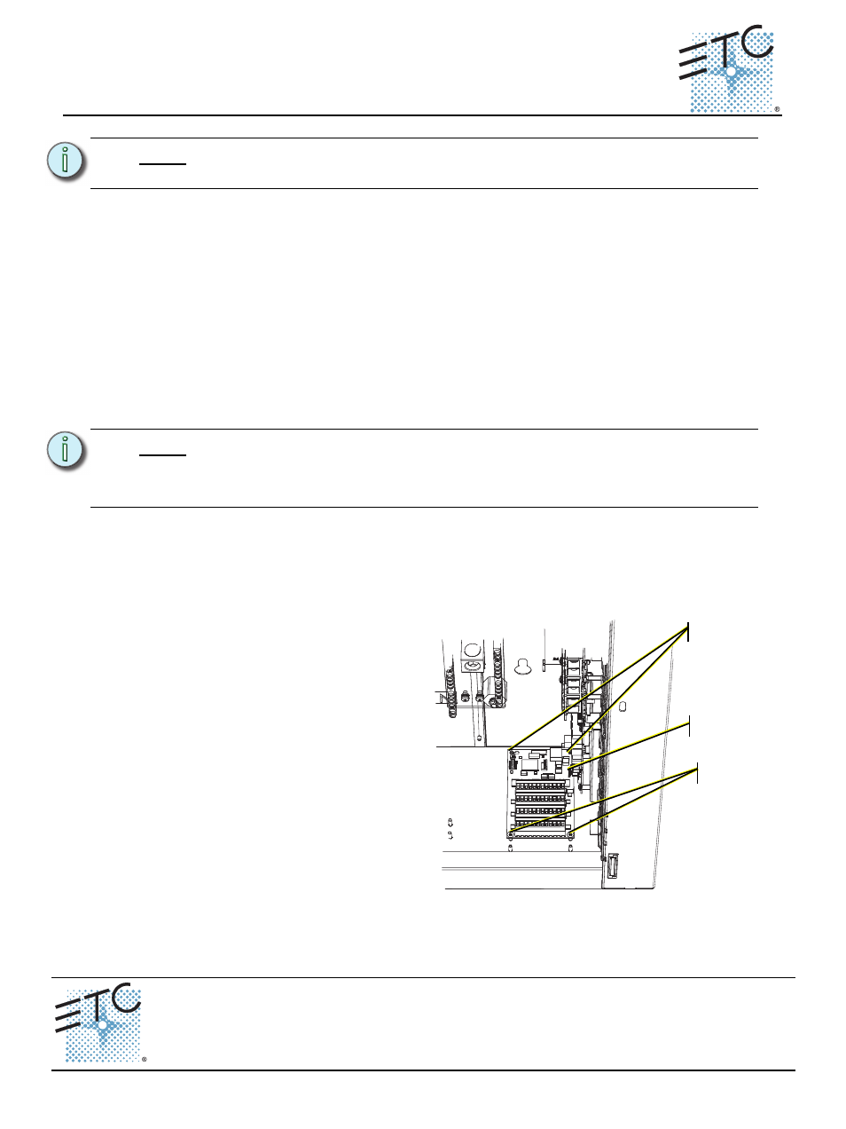
Install the DALI Option Board
Step 1:
Align the DALI option board to
the mounting studs in the
bottom right side of the DRd
rack.
• Notice the mounting holes
on the DALI option board.
One is a slotted keyhole,
another is an open ended
slot, and the remaining
two on the other end of
the board are standard
mounting holes used to
secure the board in place.
Step 2:
Set the rear left stud through
the slotted keyhole and align
the open ended slot with the
back right side mounting stud.
Step 3:
Gently slide the DALI board toward the right I/O board aligning the five prong
connector to the receptacle on the right I/O board.
Step 4:
Secure the bottom two mounting studs with the screws provided.
N o t e :
A single DRd rack supports the use of either the DALI option kit or the FLO option
kit, but not both in the same rack.
N o t e :
The DALI ballast is powered by an external DALI loop power supply (supplied by
others). This supply is connected externally of the DRd rack. Each DALI loop
requires its own power supply and possibly more than one power supply
depending on the load.
Step 2:
Step 3:
Step 4: