ETC Unison Paradigm Station Power Module (SPM) User Manual
E t c, Paradigm station power module, Installation status indicators
E T C
®
S e t u p G u i d e
Paradigm Station Power Module
Paradigm Station Power Module Setup Guide
Page 1 of 1
Electronic Theatre Controls, Inc.
Corporate Headquarters
3031 Pleasant View Road, P.O. Box 620979, Middleton, Wisconsin 53562-0979 USA
Tel +608 831 4116
Fax +608 836 1736
London, UK
Unit 26-28, Victoria Industrial Estate, Victoria Road, London W3 6UU, UK
Tel +44 (0)20 8896 1000
Fax +44 (0)20 8896 2000
Rome, IT
Via Ennio Quirino Visconti, 11, 00193 Rome, Italy
Tel +39 (06) 32 111 683
Fax +44 (0) 20 8752 8486
Holzkirchen, DE
Ohmstrasse 3, 83607 Holzkirchen, Germany
Tel +49 (80 24) 47 00-0
Fax +49 (80 24) 47 00-3 00
Hong Kong
Rm 1801, 18/F, Tower 1 Phase 1, Enterprise Square, 9 Sheung Yuet Road, Kowloon Bay, Kowloon, Hong Kong
Tel +852 2799 1220
Fax +852 2799 9325
Service: (Americas)
(UK)
(DE)
(Asia)
Web:
QSF 4.1.9.1
Copyright © 2008 ETC. All Rights Reserved.
Product information and specifications subject to change.
7182M2220
Rev A
Released 08/2008
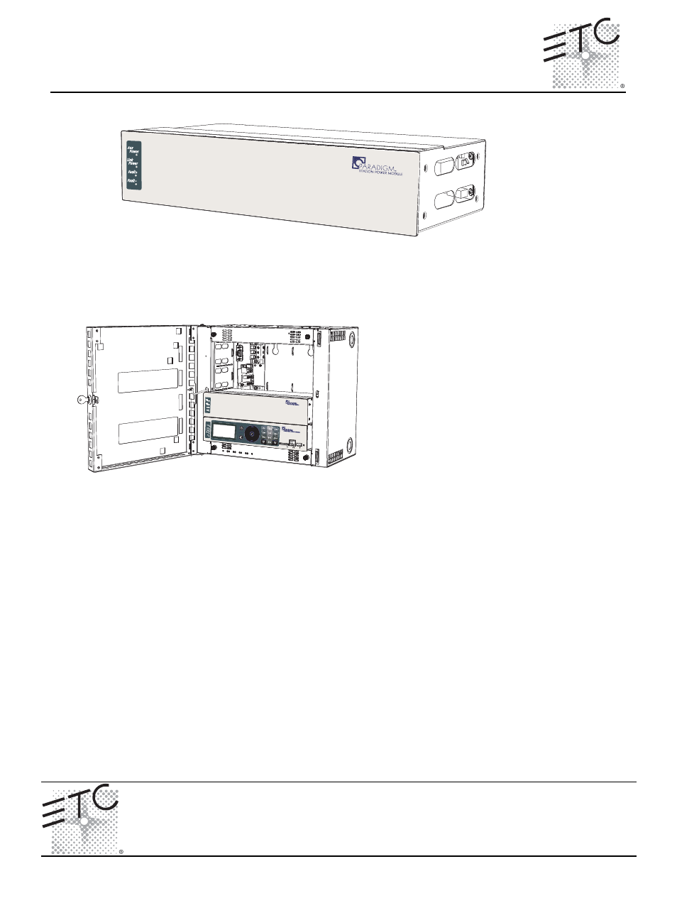
Paradigm Station Power Module
The Paradigm station power module (P-SPM) is designed for use in a DRd or ERn enclosure with
the Paradigm architectural control processor (P-ACP). The Paradigm station power module
provides power for up to 32 Unison architectural control stations on the topology-free LinkPower
control network.
Installation
Status Indicators
When power is applied to the ERn enclosure, the Paradigm station power module LEDs located on
the front panel illuminate, indicating the status of the auxiliary power, LinkPower control network,
and connected stations.
The Aux Power and LinkPower LEDs indicate in green when the Paradigm station power module is
connected properly and auxiliary power and LinkPower are present. When there is an unbalance in
LinkPower the fault indicators illuminate. This condition typically means that the station wiring has
a fault, however it could mean a connected device is having an issue. A qualified technician should
inspect the system wire and terminations first, then proceed to disconnecting devices to pinpoint
the fault and correct it. The power supply will update the fault indicators automatically when the fault
condition is cleared.
• If the NET A line has a fault (is shorted or has leakage to ground), the Fault + LED lights.
• If the NET B line has a fault (is shorted or has leakage to ground), the Fault - LED lights.
• If neither fault LED is illuminated the data connections are properly installed and the stations
are receiving the data and power required for operation.
Step 1:
Terminate station wiring as
detailed in the related
(DRd or
ERn) enclosure installation
manual
.
Step 2:
Slide the Paradigm station power
module in the module slot directly
above the Paradigm architectural
control processor.