Cabling the stack ports, Table 20: cable requirements for the stack ports, Link act – Allied Telesis AT-MCF2300 User Manual
Page 77: Sd rdy busy
AT-MCF2000 Media Converter Series Installation Guide
Section I: Features
77
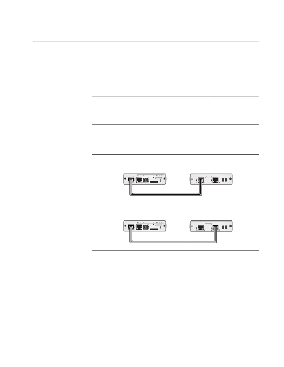
Cabling the Stack Ports
Table 20 contains the specifications for the cable for the Stack ports on the
management and stacking modules.
To cable the Stack ports, connect the Stack port on the AT-MCF2000M
Management Module to either of the Stack ports on the AT-MCF2000S
Stacking Module in the next chassis.
Figure 37. Cabling the AT-MCF2000M Management Module to the
AT-MCF2000S Stacking Module
Table 20. Cable Requirements for the Stack Ports
Cable Type
Maximum
Operating Distance
Standard straight-through or crossover TIA/EIA
568-B-compliant Enhanced Category 5 (Cat 5e)
shielded or unshielded cabling with 100 ohm
impedance.
100 m (328 ft)
AT-MCF2000S
LINK
ACT
PORT ACTIVITY
STACK 1
STACK 2
AT-MCF2000S
LINK
ACT
PORT ACTIVITY
STACK 1
STACK 2
AT-MCF2000M
STACK
MANAGEMENT
TERMINAL
10/100/1000BASE-T
RS-232
RESET
SD
RDY
BUSY
MASTER
POWER
BOOT
RDY
FAULT
1000 LINK
ACT
10/100 LINK
ACT
FDX
HDX
COL
LINK
ACT
PORT ACTIVITY
SYSTEM
0
31
ID
AT-MCF2000M
STACK
MANAGEMENT
TERMINAL
10/100/1000BASE-T
RS-232
RESET
SD
RDY
BUSY
MASTER
POWER
BOOT
RDY
FAULT
1000 LINK
ACT
10/100 LINK
ACT
FDX
HDX
COL
LINK
ACT
PORT ACTIVITY
SYSTEM
0
31
ID
CHASSIS ID
CHASSIS ID
1259
OR
AT-MCF2000M Management
Module
AT-MCF2000S Stacking
Module