Figure 2: at-mcf2000 chassis slots, Table 3: at-mcf2000 chassis slots, Management slot slot a – Allied Telesis AT-MCF2300 User Manual
Page 28: Slot b
Chapter 2: AT-MCF2000 and AT-MCF2300 Chassis
28
Section I: Features
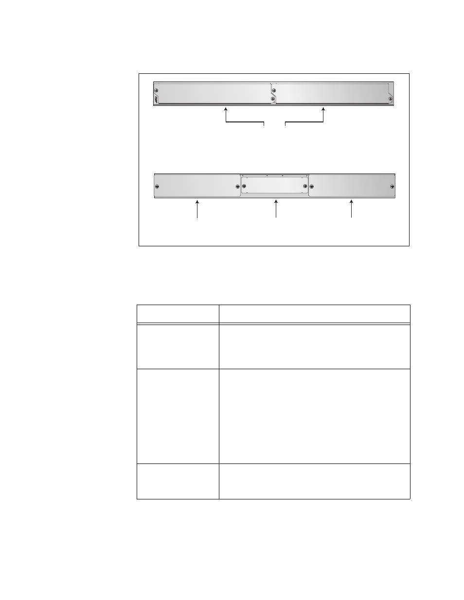
Figure 2 shows the front and back panels of the AT-MCF2000 Chassis.
Figure 2. AT-MCF2000 Chassis Slots
Table 3 lists the slots in the unit.
Table 3. AT-MCF2000 Chassis Slots
Slot
Module
1 and 2
These slots are for the multi-channel
AT-MCF2012LC, AT-MCF2012LC/1 and
AT-MCF2032SP Media Converter Modules. Each
slot can accommodate one module.
A and B
These slots are for the AT-MCF2000AC Power
Supply Module and the AT-MCF2KFAN Module.
The power requirements of the chassis can be
met with a single power supply module. A second
power supply module can be installed for power
redundancy. If the chassis has just one power
supply module, the AT-MCF2KFAN Module, a
cooling and ventilation module, must be installed
in one of these slots.
Management
This slot is for the optional AT-MCF2000M
Management Module or the AT-MCF2000S
Stacking Module.
Slots 1 and 2
1107-a
AT-MCF2KPNL1
AT-MCF2KPNL1
1
2
A
T
-MCF2000
Management
Slot
Slot A
1108-a
AT-MCF2KPNL2
AT-MCF2KPNL2
AT-MCF2KPNL3
MANAGEMENT
A
B
Slot B