Id leds, Stack port led, Id leds stack port led – Allied Telesis AT-MCF2300 User Manual
Page 70: Chassis id leds, Link/activity led, At-mcf2000m
Chapter 4: AT-MCF2000M Management Module
70
Section I: Features
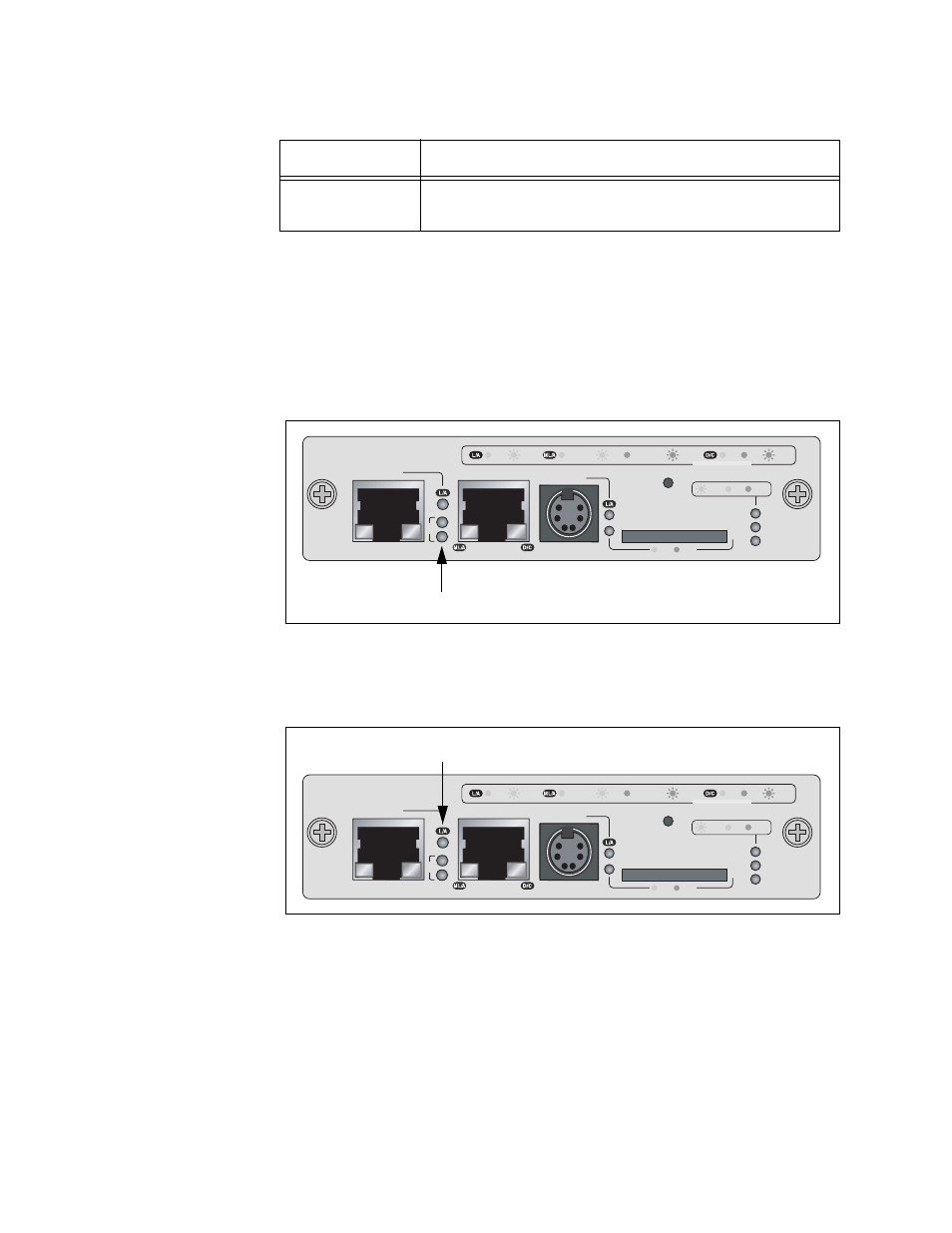
ID LEDs
The two ID LEDs are used to identify the module’s chassis ID number.
This number, which, as explained in “Chassis ID Jumper” on page 66, is
set with the jumper on the board and is used in the management
commands to identify the chassis. A management module can have the
value 0 or 31. If the ID LED 0 is on, the module and the chassis have the
ID number 0. If the ID LED 31 is on, then the module and chassis have the
ID number 31.
Figure 31. Chassis ID Number LEDs
Stack Port LED
The L/A (Link/Activity) LED on the Stack port is shown in Figure 32.
Figure 32. Link/Activity LED on the Stack Port
Flashing Amber
The port is operating in half-duplex mode with
collisions.
Table 17. Duplex-mode/Collisions LED on the Management Port
State
Description
AT-MCF2000M
STACK
MANAGEMENT
TERMINAL
10/100/1000BASE-T
RS-232
RESET
SD
RDY
BUSY
MASTER
POWER
BOOT
RDY
FAULT
1000 LINK
ACT
10/100 LINK
ACT
FDX
HDX
COL
LINK
ACT
PORT ACTIVITY
1421
SYSTEM
ID
31
0
Chassis ID LEDs
AT-MCF2000M
STACK
MANAGEMENT
TERMINAL
10/100/1000BASE-T
RS-232
RESET
SD
RDY
BUSY
MASTER
POWER
BOOT
RDY
FAULT
1000 LINK
ACT
10/100 LINK
ACT
FDX
HDX
COL
LINK
ACT
PORT ACTIVITY
1421
SYSTEM
ID
31
0
Link/Activity LED