Rdy busy, Boot rdy fault – Allied Telesis AT-MCF2300 User Manual
Page 114
Chapter 13: Installing the AT-MCF2000M Management Module
114
Section II: Installation
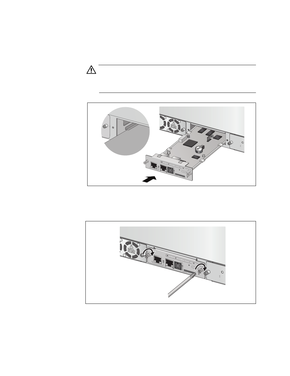
5. Align the edges of the module with the guides in the slot and carefully
slide the module into the chassis until it is flush with the front of the
chassis. Light pressure may be necessary to firmly seat the module
connector on the connector on the back panel of the chassis.
Caution
Do not force the module into place. If there is resistance, remove the
module and before reinserting it, verify that the edges of the card are
properly aligned in the guides in the chassis’ module slot.
Figure 57. Installing the Management Module
6. Secure the management module to the chassis by tightening the two
captive screws on the module with a cross-head screwdriver.
Figure 58. Securing the Management Module
AT-MCF2KF
AN
NORMA
L
FAULT
STATU
S
AT-MCF2000M
STACK
MANAGEM
ENT
TERMINAL
10/100/1000
BASE-T
RS-232
RESET
SD
RDY
BUSY
MASTER
POWER
BOOT
RDY
FAULT
1000 LINK
ACT
10/100 LIN
K
ACT
FDX
HDX
COL
LINK
ACT
PORT ACTIVITY
1200a
1201a
AT-MCF
2000
M
STACK
MANAG
EMENT
TER
MINAL
10/100
/1000
BASE-T
RS-232
RESET
SD
RDY
BUSY
MASTER
POWER
BOOT
RDY
FAULT
1000 L
INK
ACT
10/100
LINK
ACT
FDX
HDX
COL
LINK
ACT
PORT A
CTIVITY
AT-MCF2KF
AN
NORM
AL
FAULT
STAT
US