Allied Telesis AT-MCF2300 User Manual
Page 118
Chapter 14: Installing the AT-MCF2000S Stacking Module
118
Section II: Installation
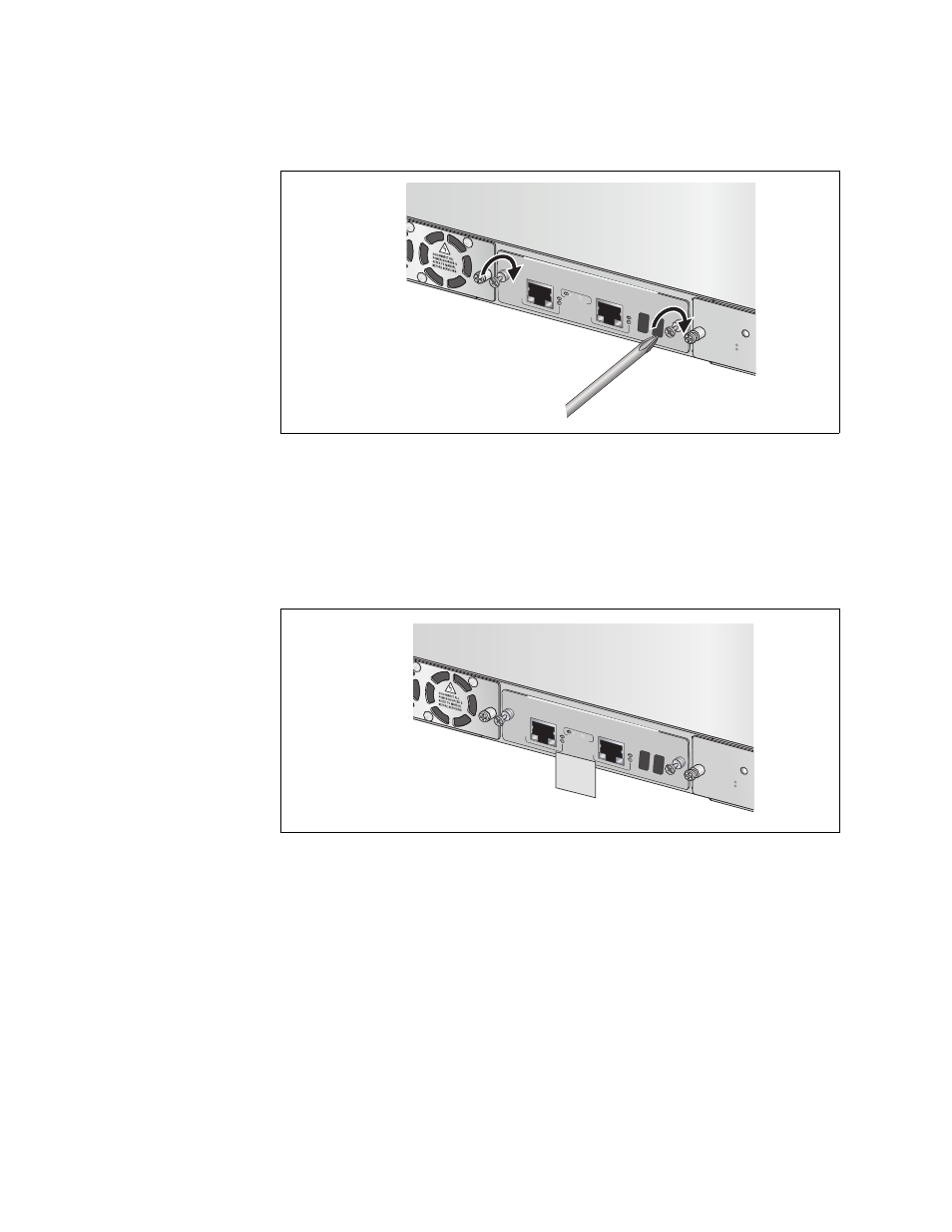
5. Secure the module to the chassis by tightening the two captive screws
with a cross-head screwdriver.
Figure 62. Securing the AT-MCF2000S Stacking Module
6. On the faceplate attach a label with the chassis ID number assigned to
the module in step 3. You’ll use the label during the verification
process later in this manual to verify the ID number of the module. The
label will also be useful in identifying the module’s chassis ID number
whenever the unit is powered off.
Figure 63. Labelling the AT-MCF2000S Stacking Module with the Chassis
ID Number
1401
AT-MCF2000
S
WER
LINK
ACT
PORT A
CTIVITY
STACK
1
CHA
SSIS ID
AT-MCF2KF
AN
NORM
AL
FAULT
STAT
US
STACK 2
1403
AT-MCF200
0S
WER
LINK
ACT
PORT
ACTIV
ITY
STACK
1
CHASSIS ID
AT-MCF2K
FAN
NORMAL
FAULT
STATUS
STACK
2
Chassis
ID 4