Leds, General status leds, Figure 28: general status leds – Allied Telesis AT-MCF2300 User Manual
Page 67: Table 14: general status leds
AT-MCF2000 Media Converter Series Installation Guide
Section I: Features
67
LEDs
The section describes the LEDs on the management module.
General Status
LEDs
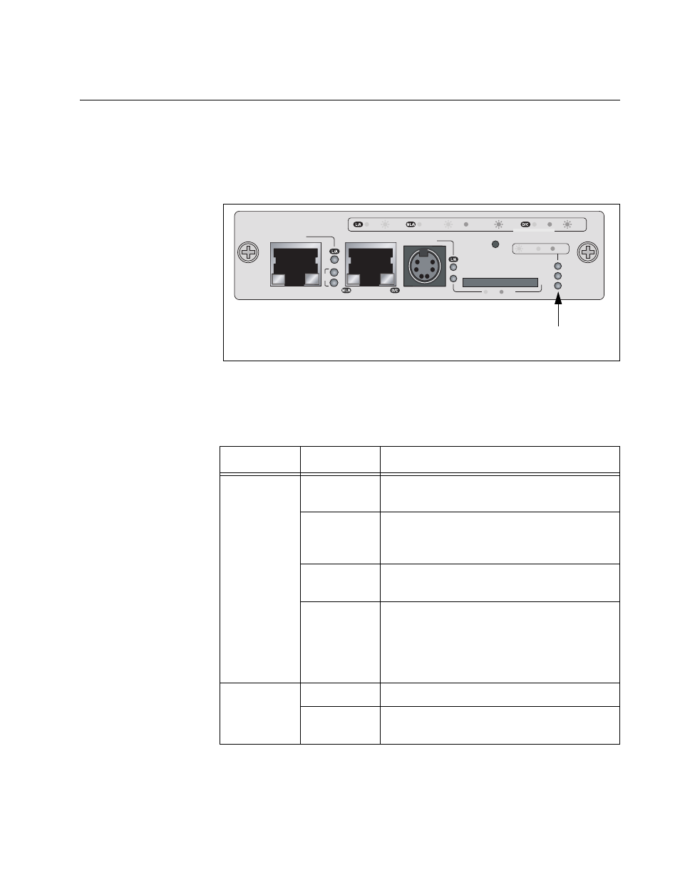
The System, Master and Power LEDs on the left side of the panel display
general status information.
Figure 28. General Status LEDs
Table 14 defines the states of the LEDs.
Table 14. General Status LEDs
LED
State
Description
System
Steady
Green
The management module is operating
normally.
Flashing
Green
The management module is initializing the
AT-S97 Management Software and
loading its active master configuration file.
Amber
The management module has
experienced a fault condition.
Flashing
Amber
The management module is receiving a
new version of the AT-S85 or AT-S97
Management Software. The destination of
the download can be the management
module or a media converter module.
Master
Off
This state is designated for future use.
Green
The module is functioning as the master
management module of the stack.
AT-MCF2000M
STACK
MANAGEMENT
TERMINAL
10/100/1000BASE-T
RS-232
RESET
SD
RDY
BUSY
MASTER
POWER
BOOT
RDY
FAULT
1000 LINK
ACT
10/100 LINK
ACT
FDX
HDX
COL
LINK
ACT
PORT ACTIVITY
1421
SYSTEM
ID
31
0
General Status
LEDs