Overview, Figure 34: at-mcf2000s stacking module – Allied Telesis AT-MCF2300 User Manual
Page 74
Chapter 5: AT-MCF2000S Stacking Module
74
Section I: Features
Overview
If you want to be able to manage all of the AT-MCF2000 and
AT-MCF2300 Chassis in your network, you could install the
AT-MCF2000M Management Module in each chassis. However, with this
approach you would have to manage the devices separately and if you
wanted to remotely manage the units, you would have to assign each
management module a unique IP address.
However, if the units are in close proximity to each other, such as in the
same wiring closet or building, there is an alternative. You could instead
link the units together with the AT-MCF2000S Stacking Module to form a
management stack. This feature lets you monitor and configure the units
with just one AT-MCF2000M Management Module and one IP address.
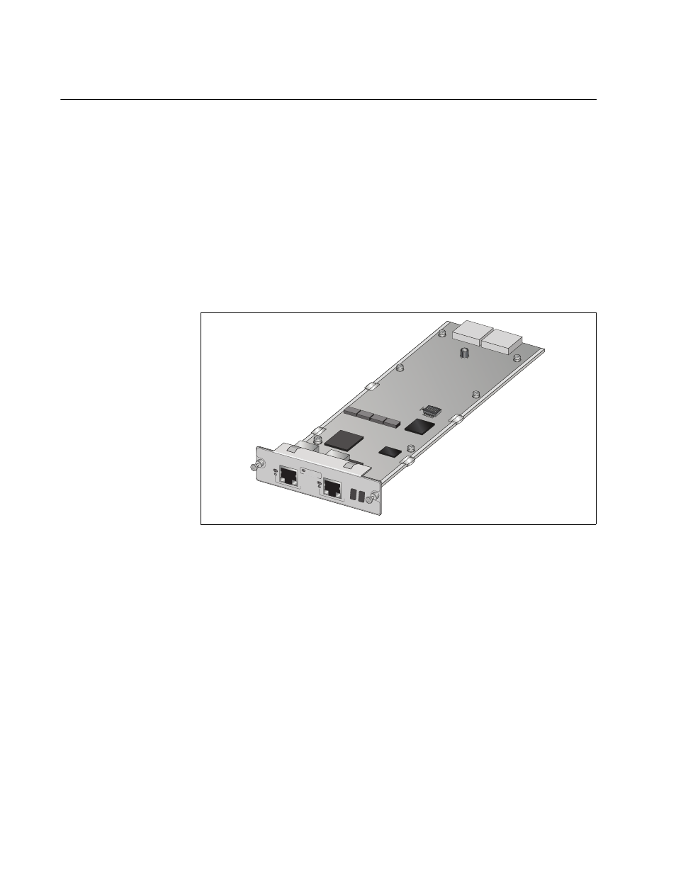
Figure 34. AT-MCF2000S Stacking Module
The stacking module has two Stack ports. The ports connect to the Stack
ports on other stacking modules and to the Stack port the management
module. The ports use standard straight-through or crossover TIA/EIA
568-B-compliant Enhanced Category 5 (Cat 5e) shielded or unshielded
cabling with 100 ohm impedance, and have a maximum cable length of
100 meters.
AT-MCF2000
S
STACK 1
LINK
ACT
POR
T ACTIV
ITY
STACK 2
CHA
SSIS ID
1264