L” link leds, Table 7: “a” activity led, Link led – Allied Telesis AT-MCF2300 User Manual
Page 42
Chapter 3: AT-MCF2012LC, AT-MCF2012LC/1 and AT-MCF2032SP Modules
42
Section I: Features
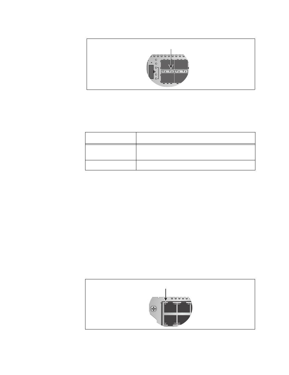
Figure 11. Activity LEDs for the Fiber Optic Ports on the AT-MCF2032SP
Module
The Activity LED is defined in Table 7.
“L” Link LEDs
The ports have Link LEDs which typically report whether or not the ports
have established links to the network devices. However, the meanings of
the LEDs can vary depending on the operating modes of the channels.
To understand the meanings of the Link LEDs of a channel, you first need
to determine a channel’s operating mode. You can do this using the
management module or the LT, ML, and SML LEDs and the Mode button
on the front panel of a module. It can also be useful to consider the Link
LEDs of the two ports of a channel as a pair and to view them as a unit.
The meanings of the Link LEDs are described in the following
subsections. There is a different subsection for each operating mode.
The Link LEDs for the twisted pair ports are located in the upper left
corners of the upper ports and the bottom left corners of the lower ports,
as shown in Figure 12.
Figure 12. Link LED for a Twisted Pair Port
Table 7. “A” Activity LED
Link LED State
Description
Off
A port is not receiving or transmitting network
packets.
Flashing Green
A port is receiving or transmitting packets.
Activity LEDs
CH
CH
CDC
FDC
LT
ML
SML
Link LED
L
A
1
L
A
2
3
4
A
T
-MCF2012LC