Media converter channels, Figure 8: channel 1 on the media converter module, Class 1 led product – Allied Telesis AT-MCF2300 User Manual
Page 34
Chapter 3: AT-MCF2012LC, AT-MCF2012LC/1 and AT-MCF2032SP Modules
34
Section I: Features
Media Converter Channels
The media converter modules have twelve independent media converter
channels that forward Fast or Gigabit Ethernet network traffic. Each
channel has one twisted pair port and one fiber optic port. The channels
on the AT-MCF2012LC and AT-MCF2012LC/1 Media Converter Modules
have 10/100Base-TX twisted pair ports and 100Base-FX fiber optic ports.
In contrast, the channels on the AT-MCF2032SP Media Converter Module
have 10/100/1000Base-T twisted pair ports and SFP slots for either 100
Mbps or 1000 Mbps fiber optic SFP modules.
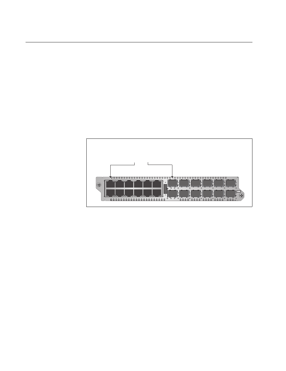
The ports of the channels are predefined. Channel 1 consists of twisted
pair port 1 and fiber optic port 1 (as shown in Figure 8), channel 2 has
twisted pair port 2 and fiber optic port 2, and so forth. You are not allowed
to alter the port assignments of the channels.
Figure 8. Channel 1 on the Media Converter Module
Each channel acts as an independent media converter. The traffic on one
channel cannot crossover to another channel. As such, local and remote
network devices that need to forward traffic to each other through the
media converter module have to be connected to ports in the same
channel. For example, for a local Fast Ethernet switch to communicate
with a remote switch, the twisted pair cable from the local switch and the
fiber optic cable from the remote switch have to be connected to ports in
the same channel, such as twisted pair port 4 and fiber optic port 4.
Devices that are connected to ports in different channels cannot
communicate with each other through the media converter module.
The ports of a channel use “store and forward” to forward traffic. A packet
is forwarded to the egress port of a channel after it has been fully received
and buffered on the ingress port and checked for CRC errors. Packets
without a CRC error are forwarded to the egress port where CRC is
regenerated prior to the transmission of the packet, while packets with
CRC errors are discarded to prevent their propagation on the network.
Channel 1
Twisted Pair Port 1 and
Fiber Optic Port 1
L
A
L
A
CH
CH
CH1
CH2
L
A
L
A
CH3
CH4
L
A
L
A
CH5
CH6
L
A
L
A
CH7
CH8
L
A
L
A
CH9
CH10
L
A
L
A
CH11
CH12
TX
RX
1
TX
RX
TX
RX
TX
RX
2
3
4
5
6
7
8
9
10
11
12
CDC
FDC
LT
ML
SML
L
A
1
L
A
2
3
4
5
6
7
8
9
10
11
12
L
A
L
A
A
T
-MCF2012LC
CLASS 1
LED PRODUCT
1119