Table 28: at-mcf2000s module items – Allied Telesis AT-MCF2300 User Manual
Page 116
Chapter 14: Installing the AT-MCF2000S Stacking Module
116
Section II: Installation
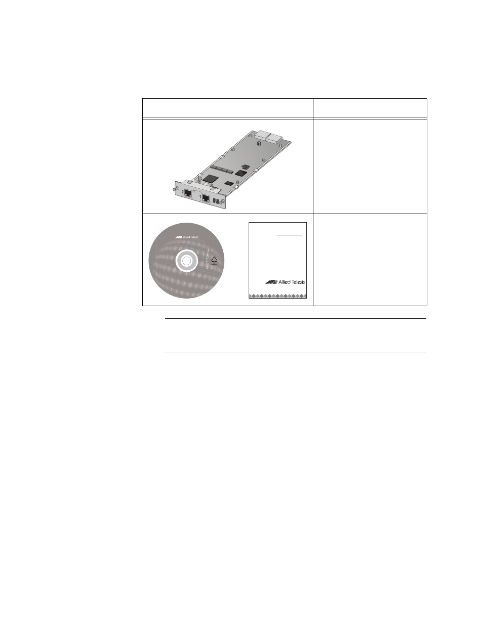
2. Unpack the AT-MCF2000S Stacking module from its shipping
container and verify the package contents listed in Table 28.
Note
You should retain the packaging material in the event you need to
return the unit to Allied Telesis.
3. Assign the module a unique chassis ID number by setting the SW2
DIP switches. (For background information, refer to “Chassis ID
Numbers” on page 79 or the AT-S85 and AT-S97 Management
Software Command Line User’s Guide.) The ID number is set with
switches 1 to 5. Switch 6 is not used. If there is tape on the DIP
switches, remove the tape. To set the switches, use a pointed object,
such as the tip of a ball point pen. The settings are listed in Table 35
on page 179 and Table 36 on page 180, and in the table printed on the
module. For example, to assign the module the chassis ID number 4,
set DIP switches 1,2, 4, and 5 to on and switch 3 to off.
Table 28. AT-MCF2000S Module Items
Component
Description
One AT-MCF2000S
Module
One Installation and User
Documentation CD or the
AT-MCF2000S Installation
Guide
AT-MCF2000
S
STACK
1
LINK
ACT
PORT
ACTIVITY
STACK
2
CHASS
IS ID
1264
1405
Stacking
Module
AT-MCF2000S
Installation
Guide
or