Table 27: at-mcf2000m management module – Allied Telesis AT-MCF2300 User Manual
Page 112
Chapter 13: Installing the AT-MCF2000M Management Module
112
Section II: Installation
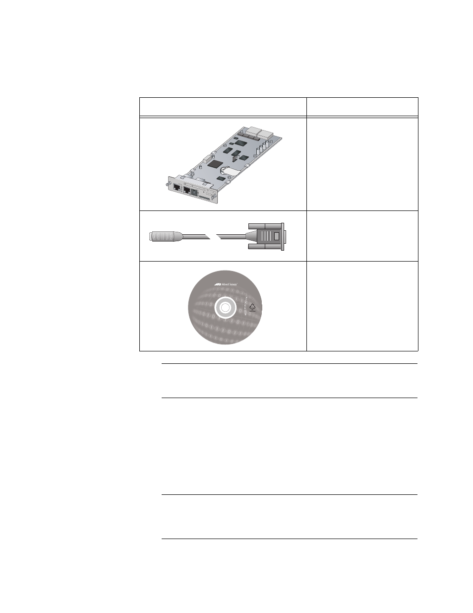
2. Unpack the AT-MCF2000M Management Module from its shipping
container and verify the package contents, listed in Table 27.
Note
You should retain the packaging material in the event you need to
return the unit to Allied Telesis.
3. If you plan to build a stack that will have two management modules,
you must change the chassis ID number of one of the modules from
the default setting 0 to 31 as shown in Figure 55. If there will be just
one management card in the stack, you can leave the jumper at the
default setting. For background information, refer to “Chassis ID
Jumper” on page 66 or the AT-S85 and AT-S97 Management
Software Command Line User’s Guide.
Note
At the time this guide was published, a stack could have only one
management module. For further information, refer to the Software
Release Notes.
Table 27. AT-MCF2000M Management Module
Component
Description
One AT-MCF2000M
Module
One management cable
with DIN-8 and DB-9
connectors
One Installation and User
Documentation CD
AT-MCF20
00M
STAC
K
MANAG
EMENT
TERMIN
AL
10/100/1
000BASE
-T
RS-232
RESET
SD
RDY
BUSY
MASTE
R
POWER
BOOT
RDY
FAULT
1000 LIN
K
ACT
10/100 L
INK
ACT
FDX
HDX
COL
LINK
ACT
POR
T ACTIVITY
1423
0
31
ID
1417
1405