Front panel, At-mcf2000m – Allied Telesis AT-MCF2300 User Manual
Page 58
Chapter 4: AT-MCF2000M Management Module
58
Section I: Features
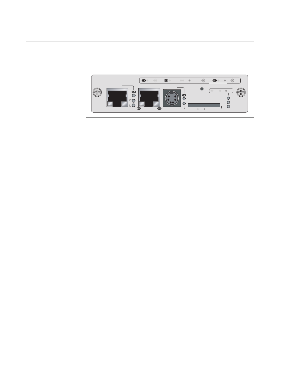
Front Panel
Figure 25 illustrates the front panel of the AT-MCF2000M Management
Module.
Figure 25. Front Panel of the AT-MCF2000M Management Module
The components on the front panel are described here:
❒
Stack port -This port is used to connect multiple chassis together so
they can be managed from one management module. For further
information, refer to Chapter 5, “AT-MCF2000S Stacking Module” on
page 73.
❒
10/100/1000Base-T Management Port - This is a standard Ethernet,
Fast Ethernet, and Gigabit Ethernet port. The module uses this port for
management functions that require communications with your
network, like remote (in-band) management from a Telnet or Secure
Shell (SSH) client and file transfers to or from a TFTP server. For
further information, refer to “10/100/1000Base-T Management Port” on
page 59.
❒
RS-232 Terminal port - You use this port for local (out-of-band)
management of the chassis. For further information, refer to “RS-232
Terminal Port” on page 61.
❒
Reset button - This button is used to perform a soft reset of the
module. It initializes the AT-S97 Management Software. For further
information, refer to “Reset Button” on page 63.
❒
SD slot - This slot is for a secure digital memory card for storing or
transferring configuration files. For further information, refer to “SD
Slot” on page 65.
AT-MCF2000M
STACK
MANAGEMENT
TERMINAL
10/100/1000BASE-T
RS-232
RESET
SD
RDY
BUSY
MASTER
POWER
BOOT
RDY
FAULT
1000 LINK
ACT
10/100 LINK
ACT
FDX
HDX
COL
LINK
ACT
PORT ACTIVITY
1421
SYSTEM
ID
31
0