Mode button, Class 1 led product, La l a – Allied Telesis AT-MCF2300 User Manual
Page 51: Tx rx 2 cdc, Ch1 x rx 2 4 cdc fdc
AT-MCF2000 Media Converter Series Installation Guide
Section I: Features
51
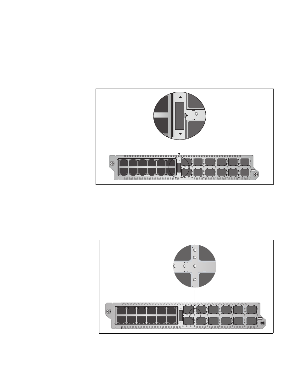
Mode Button
You use the Mode button shown in Figure 21 to set the operating modes of
the channels. You also use it to view the duplex mode and collisions on
the ports of a channel with the CDC and FDC LEDs, explained in “CDC
and FDC Duplex Mode and Collision LEDs” on page 46.
Figure 21. Mode Button
To set the operating mode of a channel or to view the duplex mode and
collisions on the ports, select the channel by turning the Mode button up or
down. Channel selection on the AT-MCF2012LC and AT-MCF2012LC/1
Modules is indicated by the numbered CH LEDs in the bottom right
corners of the fiber optic ports.
Figure 22. “CH” Channel LEDs on the AT-MCF2012LC and
AT-MCF2012LC/1 Modules
L
A
L
A
CH
CH
CH1
CH2
L
A
L
A
CH3
CH4
L
A
L
A
CH5
CH6
L
A
L
A
CH7
CH8
L
A
L
A
CH9
CH10
L
A
L
A
CH11
CH12
TX
RX
1
TX
RX
TX
RX
TX
RX
2
3
4
5
6
7
8
9
10
11
12
CDC
FDC
LT
ML
SML
L
A
1
L
A
2
3
4
5
6
7
8
9
10
11
12
L
A
L
A
A
T
-MCF2012LC
CLASS 1
LED PRODUCT
CH
CH
TX
RX
2
CDC
L
A
L
A
CH
CH
CH1
CH2
L
A
L
A
CH3
CH4
L
A
L
A
CH5
CH6
L
A
L
A
CH7
CH8
L
A
L
A
CH9
CH10
L
A
L
A
CH11
CH12
TX
RX
1
TX
RX
TX
RX
TX
RX
2
3
4
5
6
7
8
9
10
11
12
CDC
FDC
LT
ML
SML
L
A
1
L
A
2
3
4
5
6
7
8
9
10
11
12
L
A
L
A
A
T
-MCF2012LC
CLASS 1
LED PRODUCT
L
A
L
A
CH1
X
RX
2
4
CDC
FDC