Lt, ml, and sml channel operating mode leds, The cdc and fdc leds are described in table 11, Class 1 led product – Allied Telesis AT-MCF2300 User Manual
Page 48
Chapter 3: AT-MCF2012LC, AT-MCF2012LC/1 and AT-MCF2032SP Modules
48
Section I: Features
The CDC and FDC LEDs are described in Table 11.
LT, ML, and
SML Channel
Operating Mode
LEDs
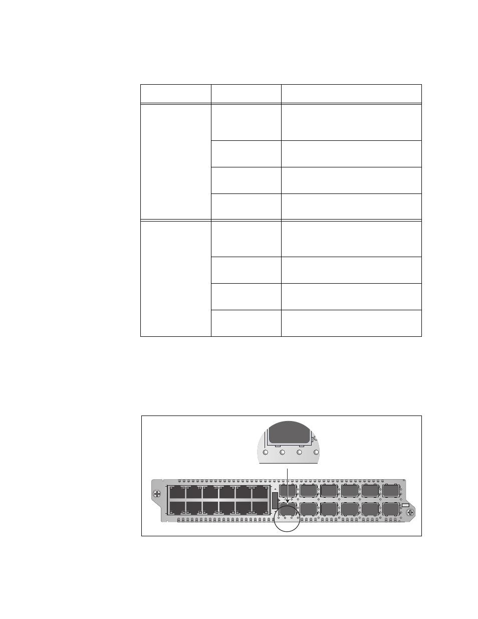
Figure 17 and Figure 18 show the locations of the LT, ML, and SML LEDs.
You use these LEDs to determine the operating modes of the channels on
the module. You can view the operating mode of just one channel at a
time with these LEDs. You select the channel with the Mode button,
explained in “Mode Button” on page 51. The operating modes are Link
Test (LT), MissingLink (ML), and Smart MissingLink (SML).
Figure 17. Channel Operating Mode LEDs on the AT-MCF2012LC and
AT-MCF2012LC/1 Modules
Table 11. CDC and FDC Duplex Mode and Collisions LEDs
LED
State
Description
CDC
Off
The twisted pair port in the channel
has not established a link with its
network device.
Steady Green
The twisted pair port is operating in
full-duplex mode.
Steady Amber
The twisted pair port is operating in
half-duplex mode.
Flashing Amber
Collisions are occurring on the
twisted pair port.
FDC
Off
The fiber optic port in the channel
has not established a link with its
network device.
Steady Green
The fiber optic port is operating in
full-duplex mode.
Steady Amber
The fiber optic port is operating in
half-duplex mode.
Flashing Amber
Collisions are occurring on the
fiber optic port.
L
A
L
A
CH
CH
CH1
CH2
L
A
L
A
CH3
CH4
L
A
L
A
CH5
CH6
L
A
L
A
CH7
CH8
L
A
L
A
CH9
CH10
L
A
L
A
CH11
CH12
TX
RX
1
TX
RX
TX
RX
TX
RX
2
3
4
5
6
7
8
9
10
11
12
CDC
FDC
LT
ML
SML
L
A
1
L
A
2
3
4
5
6
7
8
9
10
11
12
L
A
L
A
A
T
-MCF2012LC
CLASS 1
LED PRODUCT
L
A
H
CH2
LT
ML
SML