GW Instek GDM-8261A User manual User Manual
Page 89
SYSTEM/DISPLAY CONFIGURATION
89
Buffer, A/D driver and ADC vary over time, and thus the
total offset will also vary over time.
Auto Zero deducts this total offset from the measured
signal to obtain a more accurate reading. If Auto Zero is
turned off, this total offset will not be deducted from the
measured signal.
Auto zero works in the following manner:
Internally, the DMM will periodically short the Buffer’s
Hi and Lo input to obtain a total offset. The frequency at
which the offset is obtained depends on the sample rate.
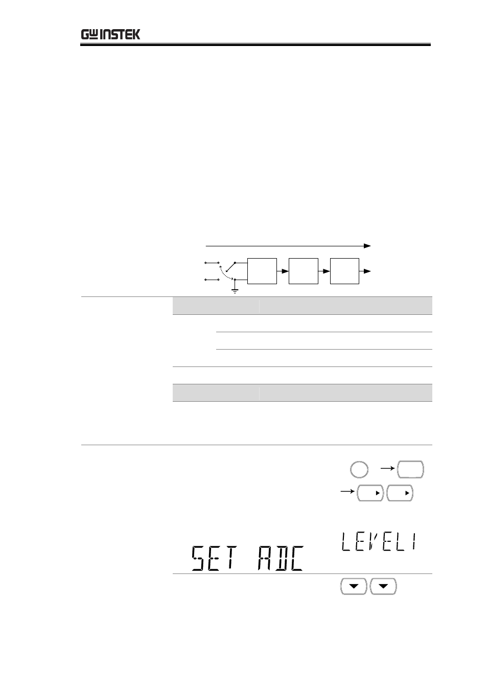
The diagram below shows how the total offset is
obtained.
Buffer
Hi
Total offset
A/D
Driver
ADC
Lo
ADC
offset
A/D Driver
offset
Buffer
offset
Input Hi
Terminal
Input Lo
Terminal
Applicable
Measurement
Mode, Rate and
Speed settings
Mode
Rate
Accuracy Speed
Quick Speed
DCV,
DCI,
4W/2W
S
M
F
Mode
Rate
TC, RTD,
Diode,
Cont
S
These four measurement modes don’t
support either accuracy or quick
speed.
M
Panel operation
1. Press the Shift key followed by
the 2nd (Menu) key. Press the
right key twice. The ADC
setting menu appears.
/ EXIT
SHIFT
2ND
MENU
TRIG
TRIG
2. Press the Down key twice. The
A-Zero setting appears.