Measuring characteristics – GW Instek GDM-8261A User manual User Manual
Page 220
GDM-8261A User Manual
220
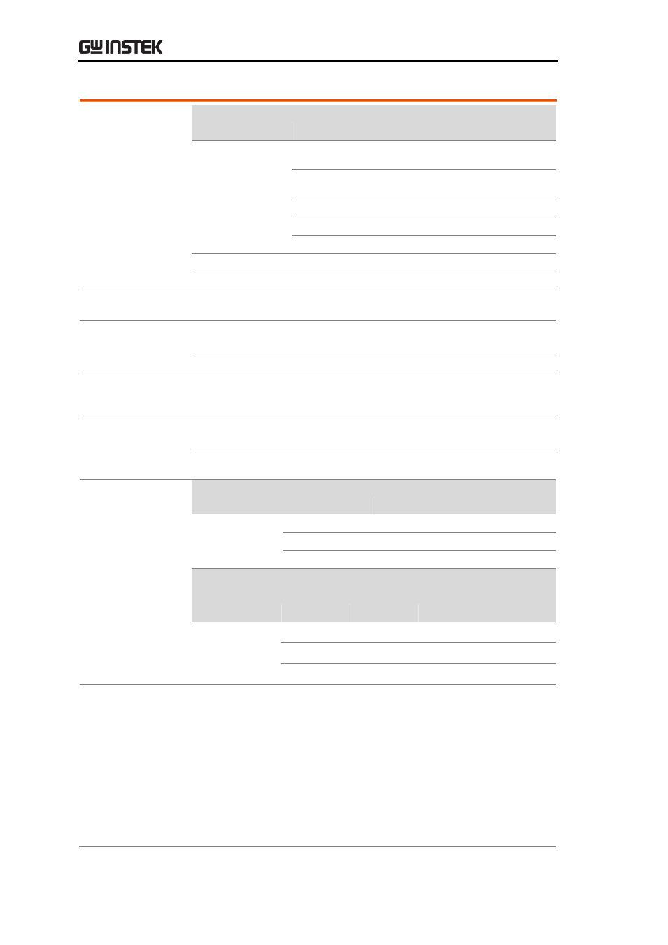
Measuring Characteristics
DC Voltage
Input
Resistance
Range
0.1V
10MΩ or >10GΩ
Selectable
1V
10MΩ or >10GΩ
Selectable
10V
11.11MΩ ±1%
100V
10.1MΩ±1%
1000V
10.1MΩ±1%
Input Bias
30pA (Typ, 25°C)
Input Protection
1000V on all ranges
Measurement Method: Sigma-delta A/D Converter
Resistance
Max. Lead
Resistance
10% of range per lead for 100Ω, 1 kΩ ranges. 1 kΩ
per lead on all other ranges.
Input Protection
1000 V on all ranges
Measurement Method: Selectable 4-wire or 2-wire ohms. Current source referenced to LO
input
DC Current
Shunt Resistor
100Ω for 100uA, 1mA. 5Ω for 10mA and 100
mA. 0.1Ω for 1A. 0.01Ω for 10A.
Input Protection
Externally accessible 1.25A, 250 V fuse; Internal
12A, 600 V fuse
Reading Rate
(Readings/sec)
[8]
Continuity/
Diode
Rate
Digits
Rate
Slow
6 ½
100
Mid
5 ½
200
Fast
4 ¼
300
DCV, DCI,
2W/4W
Resistance
Rate
Digits
Accurate Quick
Slow
6 ½
5
30
Mid
5 ½
60
600
Fast
4 ¼
240
2400
[ 1 ] For DCV/DCI/ 2/4WR measurement modes, to reach specifications
accuracy, must be set in accuracy speed, slow rate, A-Filter off, A-Gain on,
A-Zero on.
[ 2 ] For Diode/CONT/TCO/RTD measurement modes, to reach
specifications accuracy, must be set in slow rate, A-Gain on, A-Zero on.
[ 3 ] Relative to calibration standards.
[ 4 ] 20% overrange on all ranges, except 1000 Vdc and 10A range.
[ 5 ] Specifications are for 4-wire ohms function, or 2-wire ohms using REL