GW Instek GDM-8261A User manual User Manual
Page 140
GDM-8261A User Manual
140
5. To continue to the GPIB
address configuration, press the
Enter key. The GPIB address
configuration menu appears.
AUTO
ENTER
1st display
Shows the GPIB address.
2nd display
Indicates GPIB address setting
6. Change the address using the
Left/Right and Up/Down keys.
HOLD
TRIG
Range
0~30 (Default = 15)
7. Press the Enter key followed by
the Exit key. The GPIB setting
is stored and the display goes
back to the default display.
AUTO
ENTER
/ EXIT
SHIFT
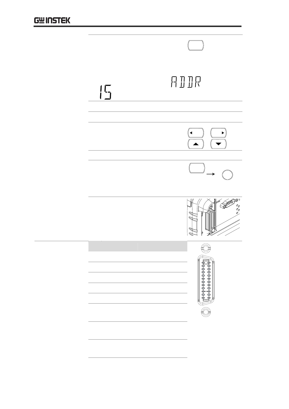
8. Connect the GPIB cable to the
rear panel optional
communication port after the
GPIB card has been installed
(page 134).
GPIB pin
assignment
Pin Signal
Pin Signal
1
12
24
13
1
Data I/O 1 13 Data I/O 5
2
Data I/O 2 14 Data I/O 6
3
Data I/O 3 15 Data I/O 7
4
Data I/O 4 16 Data I/O 8
5
EOI
17 REN
6
DAV
18 Ground
(DAV)
7
NRFD
19 Ground
(NRFD)
8
NDAC
20 Ground
(NDAC)
- GDB-03 (99 pages)
- GLA-1000 Series User Manual (111 pages)
- GLA-1000 Series Quick start guide (20 pages)
- GOS-630FC (20 pages)
- GOS-635G (36 pages)
- GOS-6000 Series (27 pages)
- GOS-6103C (30 pages)
- GOS-6100 Series (30 pages)
- GRS-6000A Series (51 pages)
- GDS-122 Installation Guide (4 pages)
- GDS-122 User Manual (52 pages)
- GDS-2000A series CAN/LIN bus User Manual (18 pages)
- GDS-2000A series Quick start guide for DS2-FGN (6 pages)
- GDS-2000A series Freewave User Manual (26 pages)
- GDS-2000A series Quick start guide for Logic analyzer option (18 pages)
- GDS-2000A series Quick start quide for DS2-LAN (2 pages)
- GDS-2000A series Option User Manual (80 pages)
- GDS-2000A series User Manual (261 pages)
- GDS-2000A series Programming Manual (272 pages)
- GDS-2000A series Single sheet for LA Quick start guide (2 pages)
- GBS-1000 Series Programming Manual (88 pages)
- GBS-1000 Series User Manual (187 pages)
- GDS-1000-U Series firmware upgrade (1 page)
- GDS-1000-U Series Programming Manual (70 pages)
- GDS-1000-U Series Quick start guide (2 pages)
- GDS-1000-U Series User Manual (133 pages)
- GDS-1000A-U Series Programming Manual (88 pages)
- GDS-1000A-U Series Quick start guide (2 pages)
- GDS-1000A-U Series User Manual (148 pages)
- GDS-3000 Series GCP-530/1030 current probe User Manual (40 pages)
- GDS-3000 Series GDP-025/050/100 differential probe User Manual (21 pages)
- GDS-3000 Series DS3-PWR Power analysis manual (37 pages)
- GDS-3000 Series User Manual (209 pages)
- GDS-3000 Series Programming Manual (103 pages)
- GDS-3000 Series DS3-SBD Serial Bus decode (29 pages)
- GDS-3000 Series GKT-100 deskew fixture User Manual (1 page)
- GDS-3000 Series GUG-001, GPIB to USB adapter User Manual (15 pages)
- GDS-300 Series User Manual (188 pages)
- GDS-300 Series Programming Manual (139 pages)
- GDS-300 Series Quick start guide (21 pages)
- GRF-3300 Series Student Manual (26 pages)
- GRF-3300 Series Teacher Manual (26 pages)
- GRF-1300A (124 pages)
- GSP-810 User Manual (40 pages)
- GSP-810 Software Manual (3 pages)