Rotate bits right (ror), C.5.8 rotate bits right (ror) – Nematron Pointe Controller User Manual
Page 402
Appendix C: Ladder Diagram Block Reference
Pointe Controller User Guide
400
Param
Name
Config
Var Type
Description
IN
Input
Value
req
any integer*
T_DONE
T_VALUE
T_PREVAL
The input value.
N
Number
of Places
req
unsigned**
T_DONE
T_VALUE
T_PREVAL
Numeric
The number of places to be
rotated.
OUT
Output
Value
req
any integer*
The result of rotating the input
value n places to the left.
* Any Input, Output, or Memory tag except 32-bit Real (F) or Bit (X). For more information, see
“
Defining Input, Output, Memory tags
” on page 114
.
** Any unsigned (UB, UW, UD, X) Input, Output, or Memory tag. For more information, see “
Defining
Input, Output, Memory tags
” on page 114
.
NOTE: If the function result is larger than the output variable (for example, a 16-
bit result to be placed in an 8-bit output variable), then the high-order bits of the
result are discarded and the low-order bits are placed in the output. No overflow
error is generated.
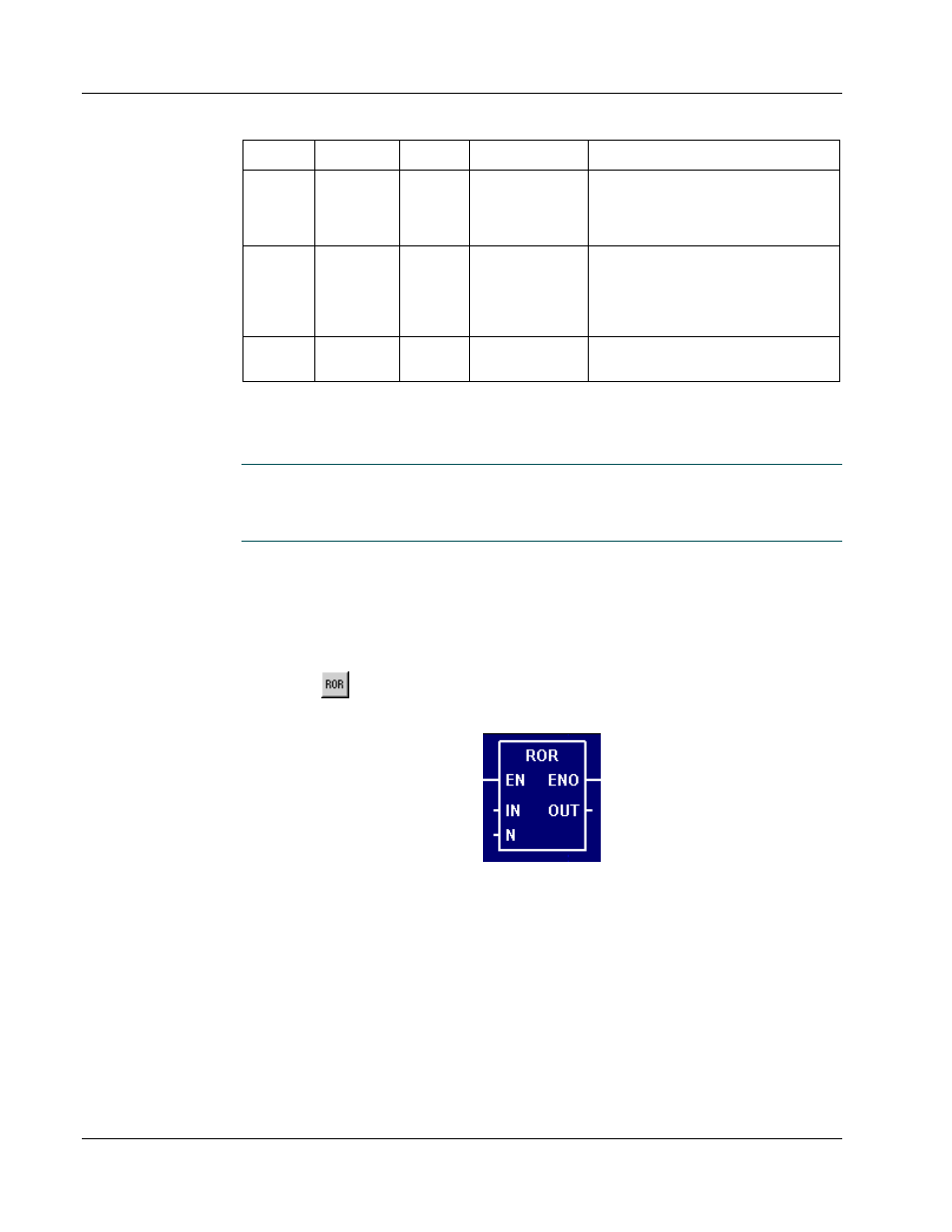
C.5.8 Rotate bits Right (ROR)
When used in a Ladder Diagram, the ROR block rotates the bits of the input a
specified number of places to the left and sends the result to output.
Select the
tool (from the
Logical and Bit Shift Blocks
toolbar) and click on a
ladder rung to insert the following block:
Once the block is inserted, you can double-click on it to
configure
it.
Functional Description
This block always passes the Enable input state (EN) through to the Enable Out
output state (ENO) without change; when EN becomes on, ENO is turned on, and
when EN becomes off, ENO is turned off.
When EN becomes on, the block function is executed: the Input Value (IN) is rotated the specified
Number of Places (N) to the right. The bits rotated off the right are added back on the left. The
resulting bit pattern is placed in the Output Value (OUT).