Logical and bit shift blocks, And (and), C.5 logical and bit shift blocks – Nematron Pointe Controller User Manual
Page 391: C.5.1 and (and)
Pointe Controller User Guide
Appendix C: Ladder Diagram Block Reference
389
C.5
Logical and Bit Shift Blocks
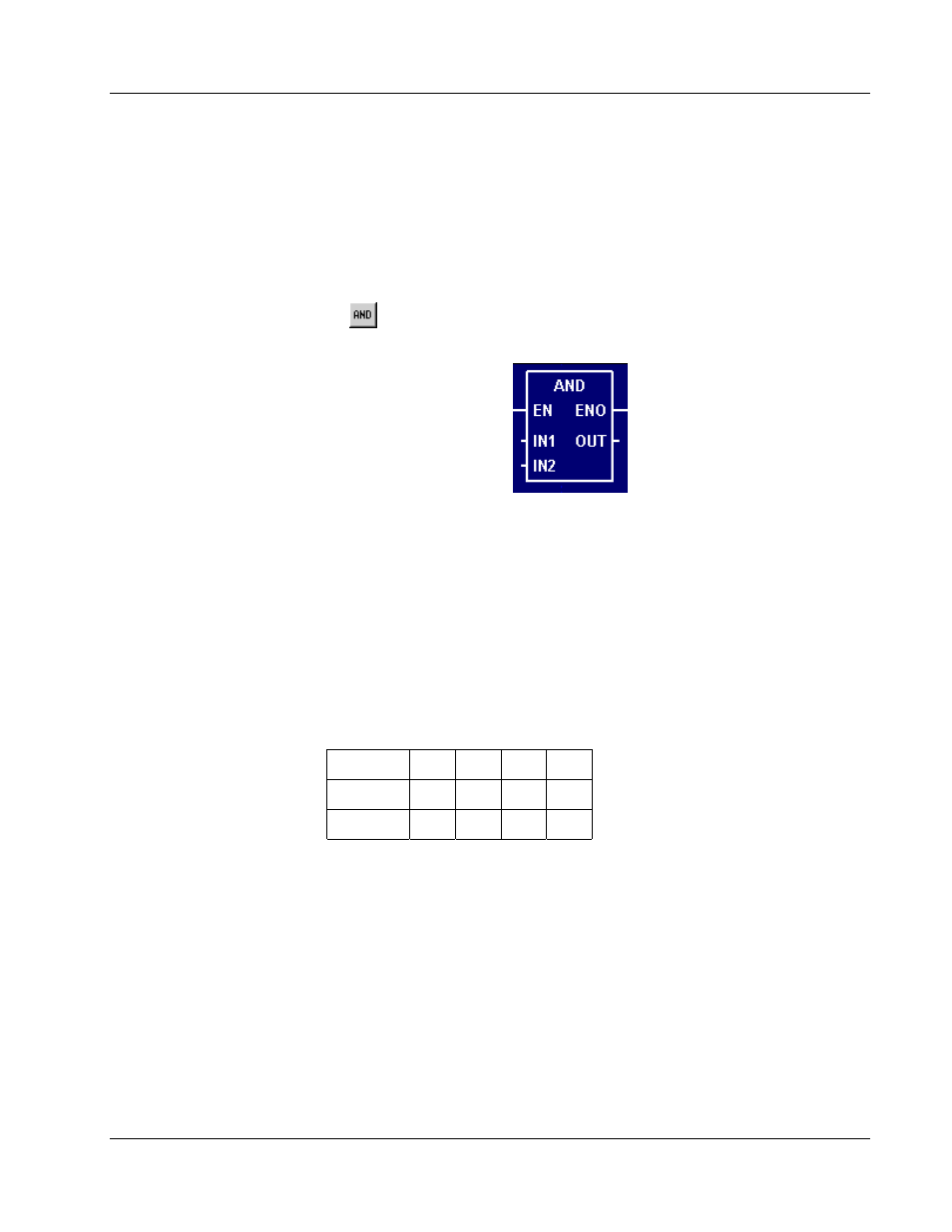
C.5.1 And (AND)
When used in a Ladder Diagram, the AND function block performs a bit-for-bit
“and comparison between two inputs and sends the result to output.
Select the
tool (from the
Logical and Bit Shift Blocks
toolbar) and click on a
ladder rung to insert the following block:
Once the block is inserted, you can double-click on it to
configure
it.
Functional Description
This block always passes the Enable input state (EN) through to the Enable Out
output state (ENO) without change; when EN becomes on, ENO is turned on, and
when EN becomes off, ENO is turned off.
When EN becomes on, the block function is executed: a bit-for-bit logical
comparison is made between the Input Values 1 and 2 (IN1 and IN2) and the
result is placed in the Output Value (OUT).
Each set of bits in IN1 and IN2 is evaluated according to the following table:
IN1
0
1
0
1
IN2
0
0
1
1
OUT
0
0
0
1
Therefore, a 16-bit example of AND would be:
IN1: 1010010101011101
IN2: 0101011010101110
OUT: 0000010000001100
The block function is executed every time the ladder is
scanned
, so long as EN
remains on. If EN becomes off, then OUT remains at its last calculated value until
EN becomes on and the block function is executed again.