Nematron Pointe Controller User Manual
Page 267
Pointe Controller User Guide
Appendix A: OptiLogic Technical Specifications
265
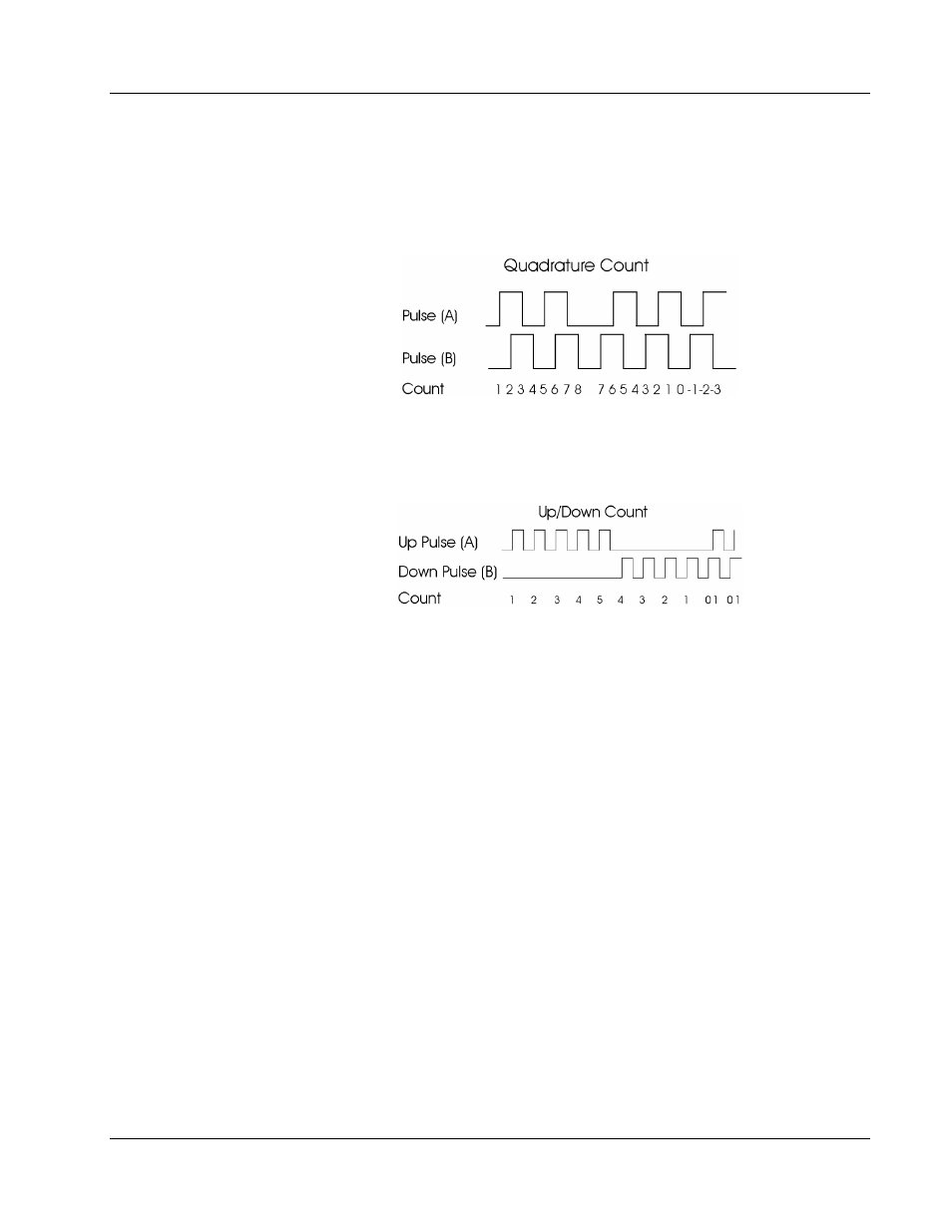
Quadrature Encoder Input
The counting process for quadrature type encoding is determined by the phase
angle between input A and input B. If A leads B, the counter increments. If B
leads A, the counter decrements. The count is incremented or decremented on
each pulse transition as shown below.
Up/Down Count
For this type of configuration, the count increments on pulses input to “A” and
decrements on pulses input to “B”. This is illustrated in the figure below.
Z and LS Presetting
The count can be preset to a value that you define based on either or both inputs
LS and Z. It can also be forced to a preset value on command via a message.
Through the configuration message, the counter can be set up to force a preset
value when Z is active, LS is active, both Z and LS are active or on software
command.
Output Control
The two open collector outputs can each be progammed to trigger within a
programmable (via an ethernet message) count range. This range can be changed
at any time via a “Send Output Range” message, effectively providing and
unlimited number of ranges, under user program control.
Outputs will trigger within immediately, when the count enters the related
range.
Frequency Measurement
Frequency data can be read back as a 16 bit signed integer value. The value will
correspond to the most recent 1 second or 200 millisecond (configurable) pulse
count.