Nematron Pointe Controller User Manual
Page 356
Appendix C: Ladder Diagram Block Reference
Pointe Controller User Guide
354
Functional Description
This block always passes the Enable input state (EN) through to the Enable Out
output state (ENO) without change; when EN becomes on, ENO is turned on, and
when EN becomes off, ENO is turned off.
When EN becomes on, the block function is executed and the following
conditions are evaluated in order:
1. If the Reset input (R) is true, then the Counter Value output (CV) is reset
to 0.
2. If R is false and the Count Up input (CU) is true, then CV is incremented
by 1.
3. If CV is greater than or equal to the Preset Value input (PV), then the
Output Up bit (QU) is set to true. If CV is less than PV, then QU is set to
false.
The block function is executed every time the ladder is
scanned
, so long as EN
remains on.
NOTE: Because the frequency of the count is based on the project’s
Scan Interval
,
it should not be used to gauge real time. To gauge real time, use a
Timer
.
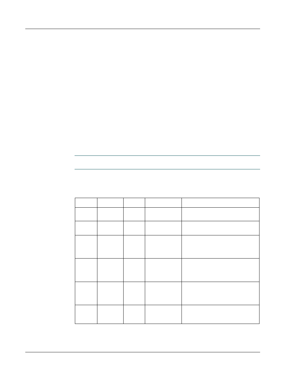
Configuration Reference
The parameters of this block are described in the following table:
Param
Name
Config
Var Type
Description
EN
Enable
no
-
The state of the rung (off/on)
received from the left.
ENO
Enable
Out
no
-
The state of the rung (off/on)
passed to the right.
CU
Count Up
req
%IX
%QX
%MX
T_DONE
The enable bit which must be set in
order for the counter to increment.
R
Reset
req
%IX
%QX
%MX
T_DONE
The reset bit; if this bit is set, then
the counter is set to 0.
PV
Preset
Value
req
%IUD
%QUD
%MUD
Numeric
The preset or target value of the
counter.
QU
Output
Up
req
%QX
%MX
The “done” bit which is set when
the counter reaches the preset
value.