1 abbreviated configuration tables, Table 8-2. analog lnput (ani) module, Table 8-3. analog output (ano) module – Micromod Micro-DCI: 53SL5100A Single Loop Controller User Manual
Page 99
Single Loop Process Controller Instruction Manual
Automatic/Manual Station 91
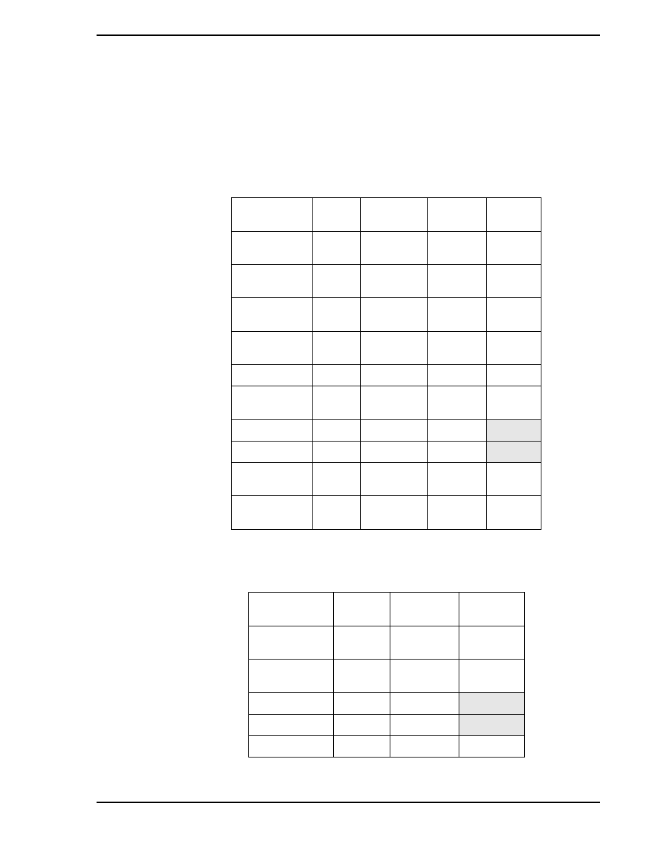
8.3.1 Abbreviated Configuration Tables
through
are provided as a quick reference source for the configuration datapoints.
These tables do not have the definition column; therefore, for the initial instrument configuration,
should be referenced until each datapoint functionality can be recognized by its title. These tables are pro-
vided because even though the functionality of the datapoints can eventually be recognized by title, the
specific datapoint locations can not always be remembered.
Table 8-2. Analog lnput (ANI) Module
Title
Symbol
ANI0
Datapoint
ANI1
Datapoint
Default
Analog Input
(Display Only)
ANI
H000
H001
0
Engineering
Span
SPAN
C256
C257
100
Engineering
Zero
ZERO
C276
C277
0
Digital Filter
Index
DFILT
B269
B270
3
0 - 5 V lnput
NOBIAS
L416
L417
0
Square Root
Signal
SQRT
L440
L441
0
Calibrate Zero
CIZ
B263
B264
Calibrate Span
CIS
C296
C297
Tag Name
AITAG
A224
A225
ANI0
ANI1
Engineering
Units
AIEU
A298
A299
Percent
Table 8-3. Analog Output (ANO) Module
Title
Symbol
ANO0
Datapoint
Default
Analog Output
(Display Only)
ANO
C000
0
0 - 210 mA
Output
OZBASE
L472
0
Calibrate Zero
COZ
B267
Calibrate Span
COS
C300
Tag Name
AOTAG
A244
ANO0