Table 4-9. parameter display module, Table 4-9 – Micromod Micro-DCI: 53SL5100A Single Loop Controller User Manual
Page 59
Single Loop Process Controller Instruction Manual
Configuration Parameters 51
Controller
Span
■
●
▲
◆
C115
100
These two parameters set the upper and
lower values on the controller display. They
permit the control action to be defined over a
range independent of the process variable
input range. They also determine the speed
at which the setpoint changes when the up or
down arrow pushbuttons are pressed (CS1
thiough CS3). For CS4, they determine only
the displayable range, as the setpoint
pushbuttons are not used.
Controller
Lower Range
■
●
▲
◆
C116
0
Control Tag
Name
■
●
▲
◆
A000
CON0
This is an assignable 10 character name that
appears with CS1-4 displays.
Engineering
Units
■
●
▲
◆
A001
Percent
The default is PERCENT, but is assignable
as units of measure the Process Variable
represents.
Note: CS1 = Single Loop (PID) Controller, CS2 = Analog Backup Controller, CS3 = Ratio Controller, and
CS4 = Automatic/Manual Station.
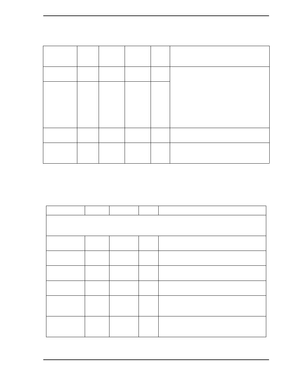
Table 4-9. Parameter Display Module
Title
Symbol
PAR1
Default
Attribute
Purpose: This module provides quick pushbutton display access to any three selected datapoints
(e.g., Alarm Limits 1 & 2 and Alarm Dead Band) without the necessity of entering Engineering mode
and addressing the datapoints.
Title
PTAG
A014
CON-0
TUNE
This is an assignable in character name that
appears with the parameter display.
Point 1 Name
PNA
A015
PROP.
BAND
This is an assignable 10 character name for the
Point 1 Designator.
Point 2 Name
PNB
A016
RESET
This is an assignable 10 character name for the
Point 2 Designator.
Point 3 Name
PNC
A017
RATE
It is an assignable 10 character name for the
Point 3 Designator.
Point 1
Designator
PDA
F087
C106
value
A database datapoint whose contents will be
displayed under the Point 1 Name (e.g., C103 to
display the Alarm Limit 1 setting).
Point 2
Designator
PDB
F088
C107
value
A database datapoint whose contents will be
displayed under the Point 2 Name (e.g., C104 to
display the Alarm Limit 2 setting).
Table 4-8. Controller Module (CON-0) (Continued)
Title
Symbol
CS
■ ● ▲ ◆
1 | 2 | 3 | 4
CON-0
Datapoint
Default
Attribute