0 front panel, 1 front panel introduction, 2 front panel display – Micromod Micro-DCI: 53SL5100A Single Loop Controller User Manual
Page 27: 0 - front panel, Figure 3-1. front panel, Section 3, front panel, This section prov
Single Loop Process Controller Instruction Manual
Front Panel 19
3.0 Front Panel
3.1 Front Panel Introduction
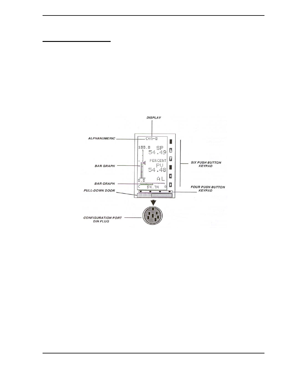
The front panel of the instrument contains the display and all push buttons used to change display presen-
tations and parameters. The front panel has a gas discharge 96 X 48 dot matrix display, a six pushbutton
vertical keypad, and a four pushbutton horizontal keypad. It also has a configuration port DIN plug, which is
concealed behind the identification tag pull-down door. To open this door, press on the lower front edge.
Front panel display information is presented as bar graphs with associated alphanumerics or as alphanu-
merics only. (See
3.2 Front Panel Display
The bar graph display is a visual indication of the process events monitored and subsequently altered
either by the instrument or other device. This instrument provides three unique bar graph displays and one
alphanumeric parameter display. Bar graph response dynamics as well as the alphanumerics on all of the
display types are selected when the instrument is configured.
There are four configurable operating modes, called control strategies (CS1-4). The control strategies are:
•
CS1, Single Loop PID Controller
•
CS2, Analog Backup Controller
•
CS3, Ratio Controller
•
CS4, Automatic/Manual Station
Two of the control strategies, CS1 and CS2, have identical bar graph presentations; that is why there are
three, rather than four, unique bar graph types. Each control strategy (CS1 - CS4) also has a pushbutton
Figure 3-1. Front Panel