0 analog backup controller, 1 analog backup controller operation overview, 0 - analog backup controller – Micromod Micro-DCI: 53SL5100A Single Loop Controller User Manual
Page 73: Figure 6-1. analog backup process loop, Section 6, analog backup controller
Single Loop Process Controller Instruction Manual
Analog Backup Controller 65
6.0 Analog Backup Controller
6.1 Analog Backup Controller Operation Overview
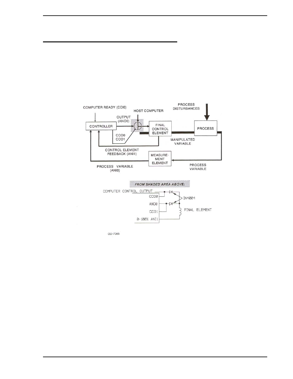
The Analog Backup Controller is used in operations where a remote computer is normally controlling the
final element directly. In this process configuration, the controller functions as a signal selector and auto-
matic backup unit to the computer. The controller assumes process control in the event of a signaled com-
puter failure. The Analog Backup Process Configuration is illustrated in
.
The Analog Backup Controller operates as a Single Loop (PID) Controller (see
) when driving the
process final element. While in backup and automatic, the controller continually adjusts its output to match
the feedback signal from the final element (Analog Input 1) so that transfer to on-line operation is bumpless
in the event of computer failure.
Selection of the computer or backup controller signals to the process final element is performed by the
controller’s CCO modules (CCO0 and CCO1) in conjunction with blocking diodes (see circuit diagram of
gray-tone area equivalent in
The computer drives the final process element when remote operation is selected at the controller front
panel via the R/L push button and if CClO’s contact is closed; otherwise, the computer’s control signal is
diverted and the controller is active. ANO0 drives the process final element (20 mA computer / 4 mA con-
troller) when backup control is active.
, Analog Backup Controller Block Diagram, when a 2 is loaded into System Mod-
ule datapoint B00 to indicate CS2, the signal designators are as follows:
Figure 6-1. Analog Backup Process Loop