2 altering a datapoint, Figure 3-10. a1 percent, Table 3-3. procedures to alter a datapoint – Micromod Micro-DCI: 53SL5100A Single Loop Controller User Manual
Page 37: Figure 3-10
Single Loop Process Controller Instruction Manual
Front Panel 29
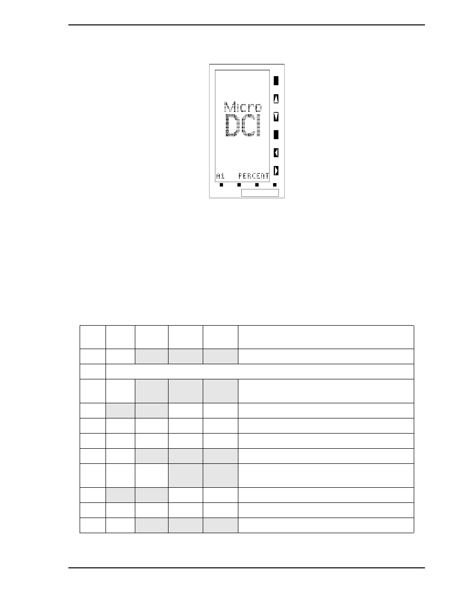
3.3.2 Altering a Datapoint
The following procedure illustrates how to enter EMODE and use the configuration function to alter the
contents of datapoint B000 (B0) with a 97. Entering a 97 in B00 invokes the display test which strobes the
display matrix dots on and off at 5 second intervals (approximate). When off, a perimeter of dots still
remains lit.
are display test illustrations that support the procedure provided in
. It should be noted that EMODE has a 20 second timeout if it is accessed and its functions (e.g.,
configure or display) are not used.
Figure 3-10. A1 PERCENT
Table 3-3. Procedures to Alter a Datapoint
Step
Press
Shift
Result
Press to
Locate
Target
Char.
Result
1
MODE
Puts instrument in EMODE.
2
If CONFIGURE does not appear, press F2.
3
F3
Displays entry line: POINT .
(If the prompt KEY? appears, see
4
↑
B
Puts B on entry line: POINT .B.
5
←
.B
∆
↑
0
Shifts B and puts 0 on entry line: POINT .B0.
6
←
.B0
∆
↑
0
Shifts B0 and puts 0 on entry line: POINT .B00.
7
F3
Displays contents of B00 (0).
8
hold
→
.
locator
B00 contents shifted right; only locator point
remains on the entry line: B00 .
9
↑
9
Puts 9 on entry line: B00 .9.
10
←
.9
∆
↑
7
Shifts 9 and puts 7 on entry line: B00 .97.
11
F3
Enters 97 in B00 to start the display test.