3 calibration, Section 12.3, Section 12 – Micromod Micro-DCI: 53SL5100A Single Loop Controller User Manual
Page 122
Single Loop Process Controller Instruction Manual
114 Maintenance
To remove the main PCB:
1.
Use the PCB’s front edge board ejector to pull it free from the rear terminal board slot, and
carefully slide it from the case.
2.
Disconnect the front display panel flat ribbon cable from the main PCB.
To install the replacement main PCB:
1.
Connect the front display panel ribbon cable.
2.
Slide the PCB into the instrument case, seating it into the rear terminal board slot.
3.
Install the front display panel.
If a situation arises requiring technical assistance, contact the nearest MicroMod Automation field office.
In the event of a hardware malfunction, a replacement PCB can be quickly substituted for the defective
assembly to minimize downtime. Contact MicroMod Automation for instructions before returning equip-
ment. The defective PCB should be carefully packaged and returned, shipping charges prepaid, to the
Repair Dept. of MicroMod Automation. Do not wrap PCBs in plastic, as it can cause static damage. It
is suggested that the defective PCB be returned in the special bag in which the replacement module was
supplied.
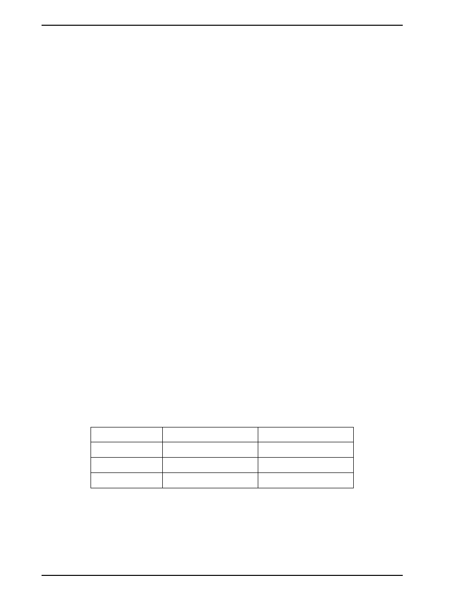
12.3 Calibration
The controller’s analog inputs (ANI0 and ANI1) and output (ANO0) are extremely stable. They normally do
not require recalibration. If it becomes necessary to recalibrate the instrument, due to the inadvertent
change of the stored calibration values, then this can be accomplished by altering their respective
datapoints. The calibration span and zero datapoint locations are shown in
.
✎ Note
Power Supply Fuses
AC Power: 1A, 250 V, Fast Blow Schurter Type 034.3930
DC Power: 3A, 250 V, Slow Blow BEL Type 5TT3
✎ Note
When communicating with MicroMod Automation for replacement
of the main PCB, refer to the serial number of the unit to ensure the
correct replacement assembly is supplied. The necessary ordering
information is provided on the instrument data tag and on the
manufacturing specification sheet supplied with that particular
controller.
Table 12-1. Calibration Span and Zero Datapoint Locations
Analog Signal
Calibrate Zero
Calibrate Span
ANI0
B263
C296
ANI1
B264
C297
ANO0
B267
C300
✎ Note
The Spans have a nominal value of 1.0 and can be adjusted up or
down within the range of 0.8 to 1.2. The Zeros have a nominal value
of 128 and can be adjusted up or down within the range of 100 to
150.