Table 4-5. analog output module, Table 4-6. contact input module, Table 4-5 – Micromod Micro-DCI: 53SL5100A Single Loop Controller User Manual
Page 54: Table 4-6
Single Loop Process Controller Instruction Manual
46 Configuration Parameters
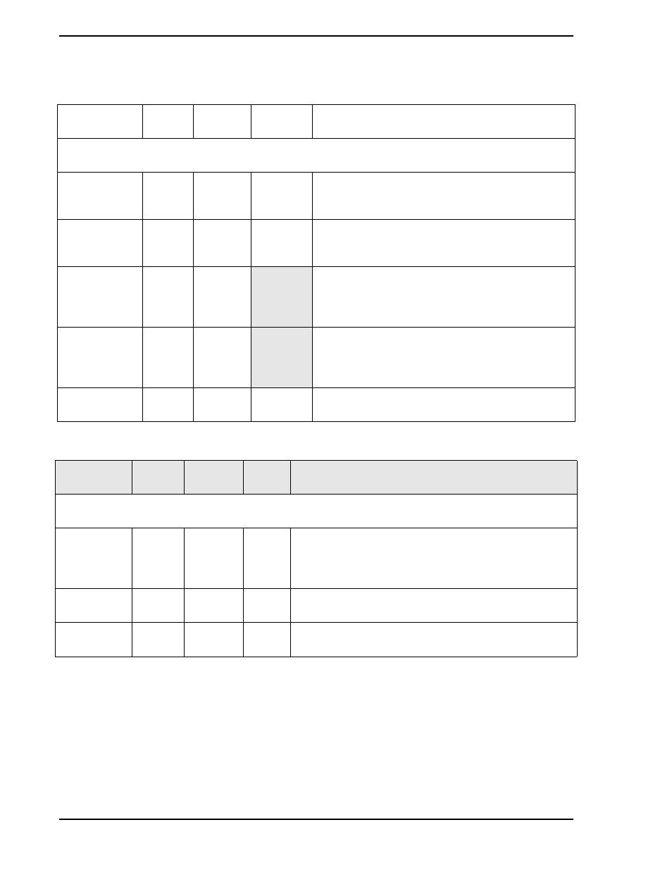
Table 4-5. Analog Output Module
Title
Symbol
ANO0
Datapoint
Default
Attribute
Purpose: The primary purpose of this module is to set the 0 - 20 mA output signal relative to the displayed
percent out.
Analog Output
(Display Only)
ANO
C000
0
The value in this datapoint represents the percent of
output to be generated by hardware (e.g., 100%
output = 20 mA).
0 - 20 mA
Output
OZBASE
L472
0
When a 0, the percentage output generates a 4 - 20
mA signal. When set to 1, the percentage output
generates a 0 - 20 mA signal.
Calibrate Zero
COZ
B267
This is the calibration zero adjustment. This
parameter is factory set and should not need
adjustment under normal operation. See
for adjustment.
Calibrate Span
COS
C300
This is the calibration span adjustment. This
parameter Is factory set and should not need
adjustment under normal operation. See
for adjustment.
Tag Name
AOTAG
A244
ANO0
It is an assignable 10 character name for the analog
output (ANO0).
Table 4-6. Contact Input Module
Title
Symbol
ANO0
Datapoint
Default
Attribute
Purpose: The primary purpose allows the action of the CCI to be reversed (normally a closed contact = 1,
but can be changed to = 0).
Contact Input
(Display Only)
CCI
L000
0
When open, a 4 - 24 V dc input signal = 0 when INV = 0.
When open, a 4 - 24 V dc input signal = 1 when INV = 1.
When closed, a < 1 V dc input signal = 1 when INV = 0.
When closed, a < 1 V dc input signal = 0 when INV = 1.
Contact Input
Invert
IINV
L264
0
As shown above, it reverses the action of the CCI
datapoint.
Tagname
CITAG
A262
CCI0
It is an assignable 10 character name for the contact
control input.