Table c-2. database (continued) – Micromod Micro-DCI: 53SL5100A Single Loop Controller User Manual
Page 145
Single Loop Process Controller Instruction Manual
Database 137
Control
Alarm Mode
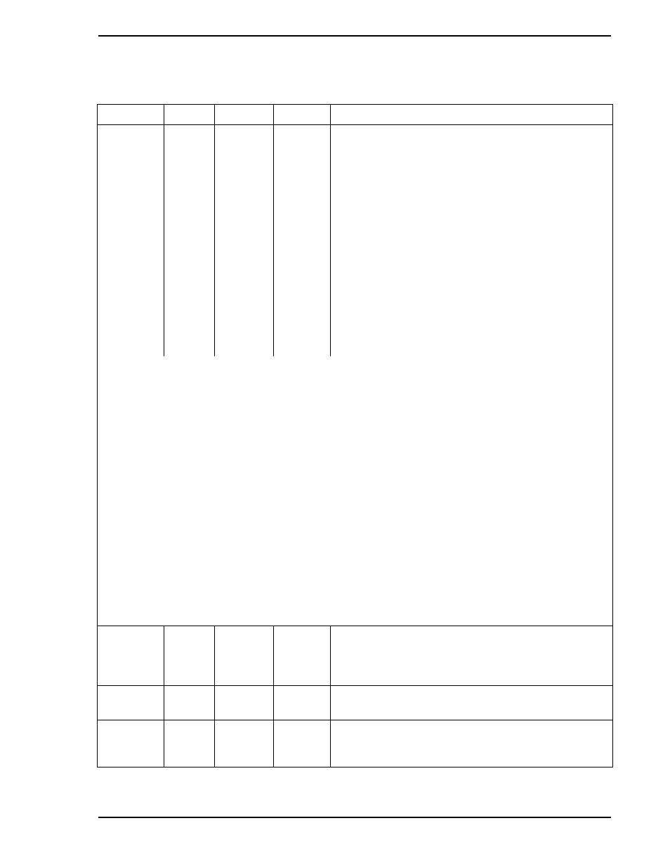
AIX
B335
1
This parameter defines the Alarm Active (PA1 & PA2)
interpretation of the two Alarm Limits (PL1 & PL2). It is
entered into the datapoint as an index value (0-6) as
follows:
0 PA1: High when PV > PL1
PA2: Low when PV < PL2
1 - None
2 PA1: High when PV > PL1
PA2: not affected
3 PA1: not affected
PA2: Low when PV < PL1
4 PA1: High when PV > PL1
PA2: Hi-Hi when PV > PL2
5 PA1: Low when PV < PL1
PA2: Lo-Lo when PV < PL2
6 PA1: Hi-Dev when Dev > PL1
PA2: Lo-Dev when Dev < PL2
Alarm Examples:
B335 PV PL1 PL2 Alarm Setpoint Notes
(C103) (C104)
0 >60 60 HIGH Alarm Limit 1 is set for 60. If PV exceeds 60 = HIGH alarm.
0 <40 40 LOW Alarm Limit 2 is set for 40. If PV falls below 40 = LOW alarm.
2 >60 60 HIGH Alarm Limit 1 is set for 60. If PV exceeds 60 = HIGH alarm.
2 <40 40 N/A Alarm Limit 2 is set fo 40. If PV falls below 40 = no alarm condition.
3 >60 60 N/A Alarm Limit 1 is set for 60. It PV exceeds 60 = no alarm condition.
3 <40 40 LOW Alarm Limit 2 is set for 40. If PV falls below 40 = LOW alarm.
4 >60 60 HIGH Alarm Limit 1 is set for 60. If PV exceeds 60 = HIGH alarm.
4 >70 70 HI-HI Alarm Limit 2 is set for 70. If PV exceeds 70 = HI-HI alarm.
5 <40 40 LOW Alarm Limit 1 is set for 40. If PV falls below 40 = LOW alarm.
5 <30 30 LO-LO Alarm Limit 2 is set for 30. If PV falls below 30 = LO-LO alarm.
6 >50 10 HI-DEV 40 Alarm Limit 1 = 10, Setpoint at 40. If PV exceeds 50 = HI-DEV alarm.
6 <30 -10 LO-DEV 40 Alarm Limit 2 = -10, Setpoint at 40. If PV falls below 30 = LO-DEV alarm.
Analog
Output
(Display
Only)
ANO0
C000
0
The value in this datapoint represents the percent of
output to be generated by hardware (e.g., 100 % output =
20 mA).
Process
Variable
PV
C100
0
This is the actual PV variable of the controller PID
algorithm. It is obtained from ANI0.
Setpoint
SP
C101
0
This is the actual setpoint of the PID algorithm obtained
from the setpoint increase/decrease pushbuttons or from
Remote Setpoint (RSP).
Table C-2. Database (Continued)
Title
Symbol Datapoint
Default
Attribute