3 ratio controller parameter selections, Figure 7-4. cs3 datapoint selections – Micromod Micro-DCI: 53SL5100A Single Loop Controller User Manual
Page 88
Single Loop Process Controller Instruction Manual
80 Ratio PID Controller
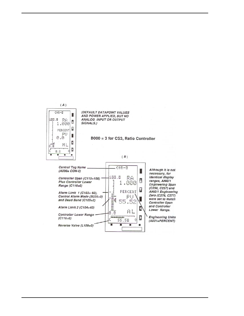
7.3 Ratio Controller Parameter Selections
illustrates how a Ratio Controller would appear with only the default values and power applied,
but no analog input or output signals. In
, ANO0 (TB1-10) is jumpered to ANI0 (TB1-2) to simu-
late process operation. The unit has the AC power supply and power cord 173D109U03. Connecting
ANO0 to ANI0 is done only for illustration purposes and is not necessary to configure the controller. If the
controller is connected to a Datalink network, then assign the Instrument Address (B001) and Baud Rate
(B002) first so the remaining datapoints may be entered at the SUPERVISOR-PC unit.
After this section, refer to
to configure the parameter display datapoints. The parameter display
is accessed by pressing the
F2 push button from this display. Also, refer to
, to set the operating performance parameters: Proportional Band
(C106), Reset Time (C107), and Rate Time (C108). All other datapoints not shown in the illustration are at
the default value.
Figure 7-4.
CS3 Datapoint Selections