Figure 5-2. single loop controller block diagram – Micromod Micro-DCI: 53SL5100A Single Loop Controller User Manual
Page 64
Single Loop Process Controller Instruction Manual
56 Single Loop (PID) Controller
to the final element to restore the process. The output signal (Analog Output) to the final element is 4-20
mA dc. This signal is also factory calibrated for zero and span, and should not be altered. On the controller
display, the output signal value correlates to the desired control element operation (e.g., an output of 100%
equals a 20 mA signal amplitude, which causes a valve to be fully opened or closed, depending on the
reverse valve setting in the Single Loop Controller).
Single Loop Controller output response characteristics to the process changes are determined by Propor-
tional, Integral, and Derivative parameters (also called PID constants). The controller PID constants, as
well as other controller functions (e.g., reverse valve), can be defined with configuration datapoint
parameter entries. The PID general response characteristics are defined in
.
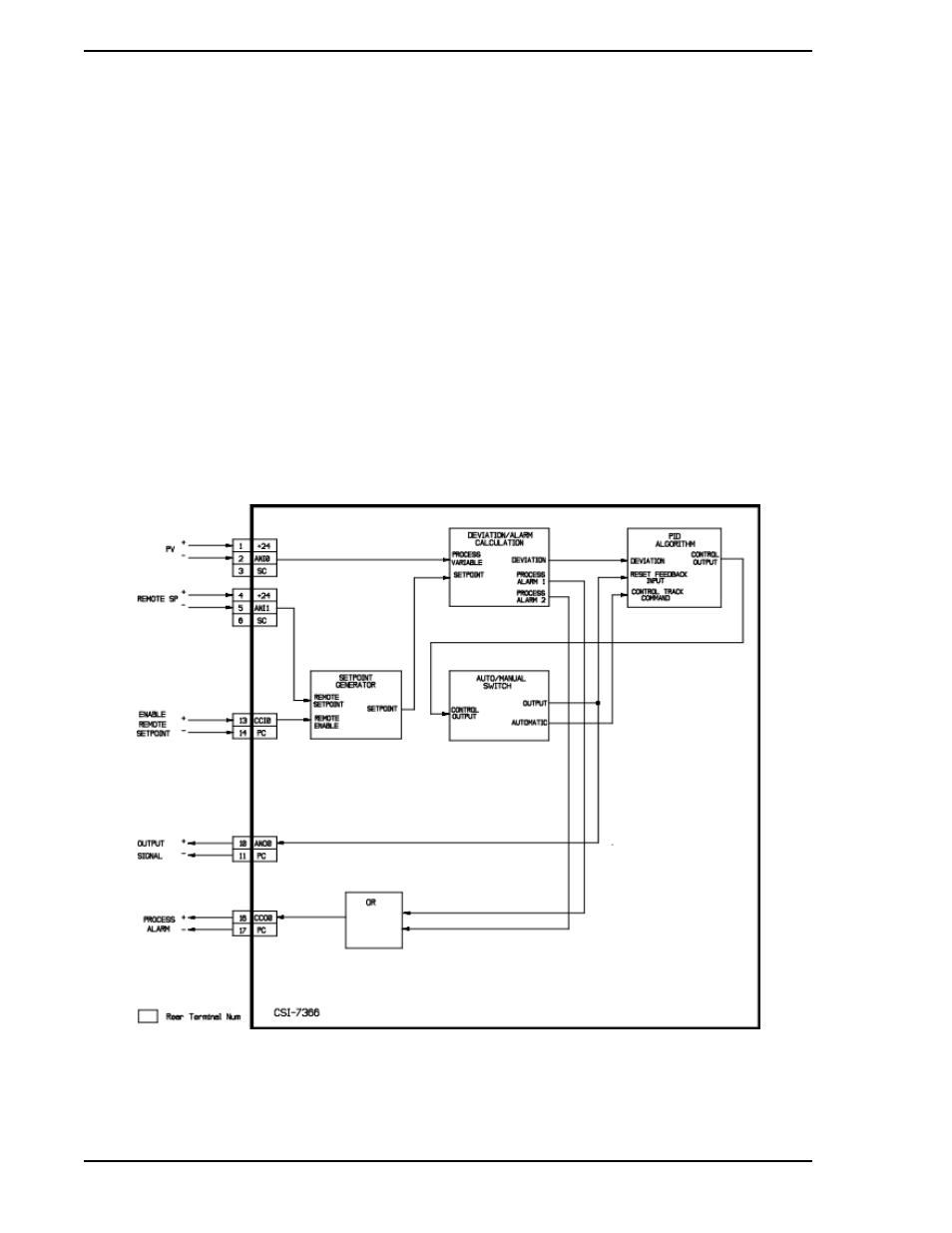
, Single Loop Controller Block Diagram, when a 1 is loaded into System Module
datapoint B00 to initiate CS1, the signal designators are as follows:
1.
ANI0 = Process Variable Input
2.
ANI1 = Remote Setpoint Input
3.
ANO0 = Controller Output
4.
CCI0 = Enable Remote Setpoint
5.
CCO0 = Process Alarm
Figure 5-2. Single Loop Controller Block Diagram