Table 4-8. controller module (con-0), Table 4-8 – Micromod Micro-DCI: 53SL5100A Single Loop Controller User Manual
Page 57
Single Loop Process Controller Instruction Manual
Configuration Parameters 49
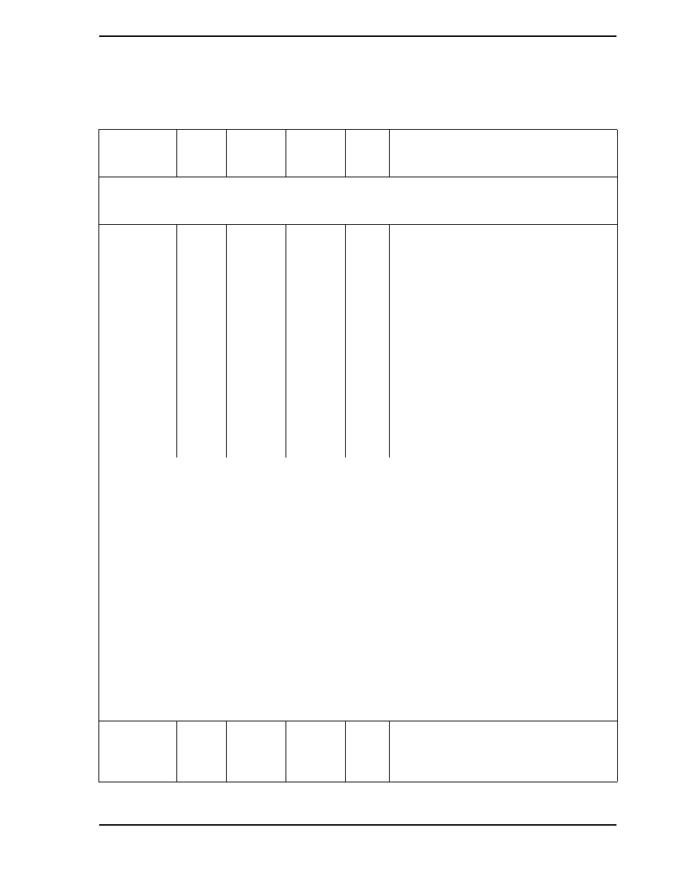
Table 4-8. Controller Module (CON-0)
Title
Symbol
CS
■ ● ▲ ◆
1 | 2 | 3 | 4
CON-0
Datapoint
Default
Attribute
Purpose: The primary purpose of this module is to set the instrument’s responsiveness, Alarm Limits 1 &
2, Alarm Dead Band, and the range limits (e.g., 0 - 100, -20 - 80, etc.).
Note:
■ ● ▲ ◆ = applicable to the Control Strategy (CS) as shown in column three.
Control Alarm
Mode
AIX
■
●
▲
◆
B335
1
This parameter defines the Alarm Active
(PA1 & PA2) interpretation of the two Alarm
Limits (PL1 & PL2). It is entered into the
datapoint as an index value (0-6) as follows:
0 PA1: High when PV > PL1
PA2: Low when PV < PL2
1 - None
2 PA1: High when PV > PL1
PA2: not affected
3 PA1: not affected
PA2: Low when PV < PL1
4 PA1: High when PV > PL1
PA2: Hi-Hi when PV > PL2
5 PA1: Low when PV < PL1
PA2: Lo-Lo when PV < PL2
6 PA1: Hi-Dev when Dev > PL1
PA2: Lo-Dev when Dev < PL2
Alarm Examples
B335 PV PL1 PL2 Alarm Setpoint Notes
(C103) (C104)
0 >60 60 HIGH Alarm Limit 1 is set for 60. If PV exceeds 60 = HIGH alarm.
0 <40 40 LOW Alarm Limit 2 is set for 40. If PV falls below 40 = LOW alarm.
2 >60 60 HIGH Alarm Limit 1 is set for 60. If PV exceeds 60 = HIGH alarm.
2 <40 40 N/A Alarm Limit 2 is set fo 40. If PV falls below 40 = no alarm condition.
3 >60 60 N/A Alarm Limit 1 is set for 60. It PV exceeds 60 = no alarm condition.
3 <40 40 LOW Alarm Limit 2 is set for 40. If PV falls below 40 1 LOW alarm.
4 >60 60 HIGH Alarm Limit 1 is set for 60. If PV exceeds 60 = HIGH alarm.
4 >70 70 HI-HI Alarm Limit 2 is set for 70. If PV exceeds 70 = HI-HI alarm.
5 <40 40 LOW Alarm Limit 1 is set for 40. If PV falls below 40 = LOW alarm.
5 <30 30 LO-LO Alarm Limit 2 is set for 30. If PV falls below 30 = LO-LO alarm.
6 >50 10 HI-DEV 40 Alarm Limit 1 = 10, Setpoint at 40. If PV exceeds 50 = HI-DEV alarm.
6 <30 -10 LO-DEV 40 Alarm Limit 2 = -10, Setpoint at 40. If PV falls below 30 = LO-DEV alarm.
Control Action
RSW
■
●
▲
◆
L106
1
When set to a 0, the controller output
increases as the process value increases.
When set to a 1, the controller output
decreases as the process value increases.