Eisa to edr interface, Lpci bus, Eisa to lpci interface – Grass Valley PDR 200 Service Manual User Manual
Page 42: Eisa dma controller
Chapter 3 Theory of Operation
3-10
PDR 200 Service Manual
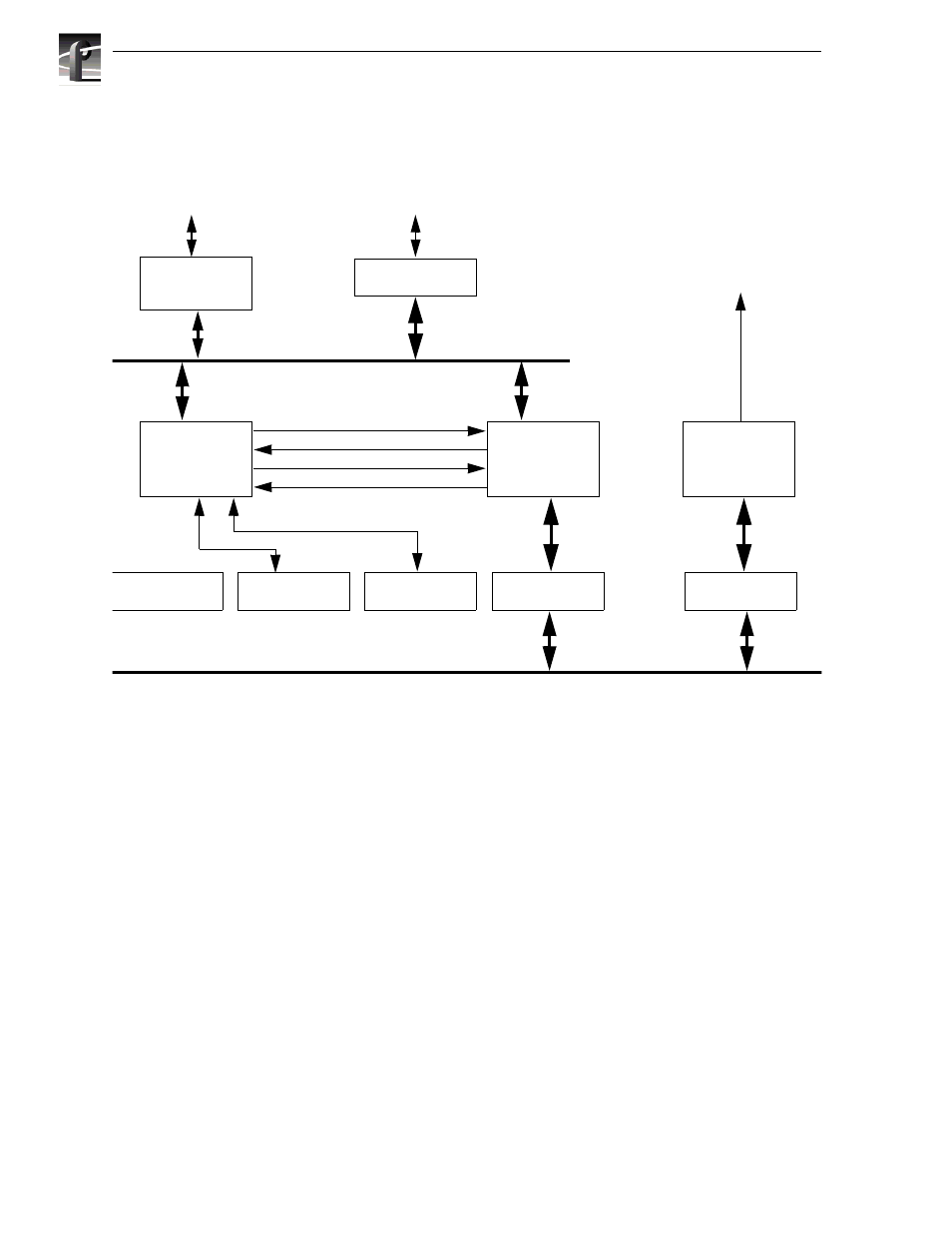
EISA to EDR Interface
The EISA to EDR bus interface is provided by the EISA_PLDs EISA slave interface.
Figure 3-4 shows a block diagram of this interface.
Figure 3-4. Block Diagram - EISA to EDR Interface
LPCI Bus
The local PCI (LPCI) bus provides an internal PCI bus connecting the two SCSI
controllers and the JPEG control logic. The LPCI also contains a bridge to the GPCI
bus and a interface which allows the EISA bus access to the LPCI.
EISA to LPCI Interface
The EISA to LPCI interface is provided by the EISA_PLD chip, the IB_FIFO chip,
and a set of switch parts. When the EISA_PLD decodes the EISA address as being
targeted for the LPCI bus, it requests mastership of the LPCI bus. When it is granted
LPCI mastership, the set of switches, which electrically connect the IB_Bus to the
LPCI bus, are enabled. This interface again allows an EISA master to do single word,
half word, and byte accesses to the LPCI bus.
EISA DMA Controller
The EISA DMA controller is implemented in the EISA_PLD, along with the
IB_FIFO chip. It provides a high bandwidth connection between the JPEG memory
buffers and external EISA slaves, such as the audio boards. The EISA_PLD contains
registers which control the DMA engine.
LPLX
PLX9060ES
Quick Switches
Addr Xcvrs
Output Buffer
Input Buffer
Data Xcvrs
Data Xcvr
EISA_PLD
81500a
EISA FIFO
74ABT3615
EISA Board
Control 7128
LPCI Bus
RTP Bus
IB_PCI Bus
Board
Control
Signals
EISA Bus