Grass Valley PDR 200 Service Manual User Manual
Page 126
Chapter 6 Parts Removal and Replacement
6-34
PDR 200 Service Manual
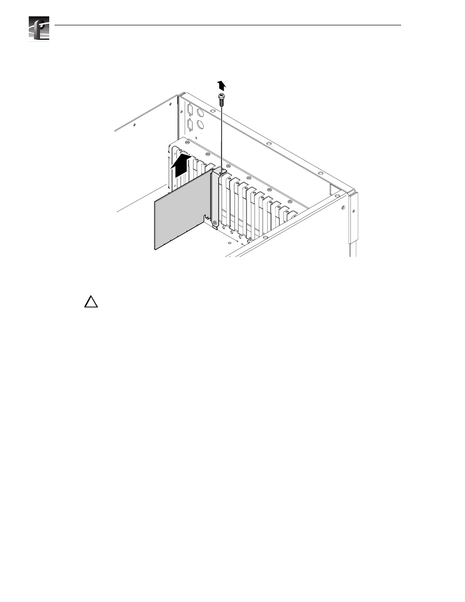
Figure 6-21. Removal of a Short Board
CAUTION: To prevent damage, do not rock the circuit board in the EISA Bus
connector. Pull straight up to remove.
4. For a full-size board, use the extraction lever on the front of the board and the
extraction ring at the back of the board to lift the board free of the Motherboard
connectors and then lift the board up and out of the Profile chassis.
To reinstall a board:
1. Carefully slide the circuit board into the connectors on the Motherboard. Full-size
boards have a guide at the front and an extractor. The extractor must be in the up
position and aligned with the notch in the front guide during insertion. Some
resistance will be exerted by the contact pressure of the connectors. Take care not to
exert excess force to seat a board.
2. Use the Torx tool with the T15 tip to install any board mounting screw(s) previously
removed.
3. Using your diagram, reconnect all internal cabling.
4. Perform the board retainer bracket installation procedure (page 6-32).
9675-13
!!