Serial emi board, Serial emi board -37 – Grass Valley PDR 200 Service Manual User Manual
Page 129
Serial EMI Board
PDR 200 Service Manual
6-37
Serial EMI Board
The Serial EMI board assists in maintaining the environmental integrity of the
PDR 200 when RS-232 devices are connected to the rear panel serial connectors.
Removal and installation requires removal of both covers and removal of as many
boards as necessary to access the Serial EMI board.
To remove the Serial EMI board:
1. Turn PDR200 power Off and disconnect the power cord.
2. Perform the procedure to remove the Profile chassis from the rack (page 6-6).
3. Remove the Profile chassis covers (page 6-8).
4. Remove as many boards as necessary to access the Serial EMI board.
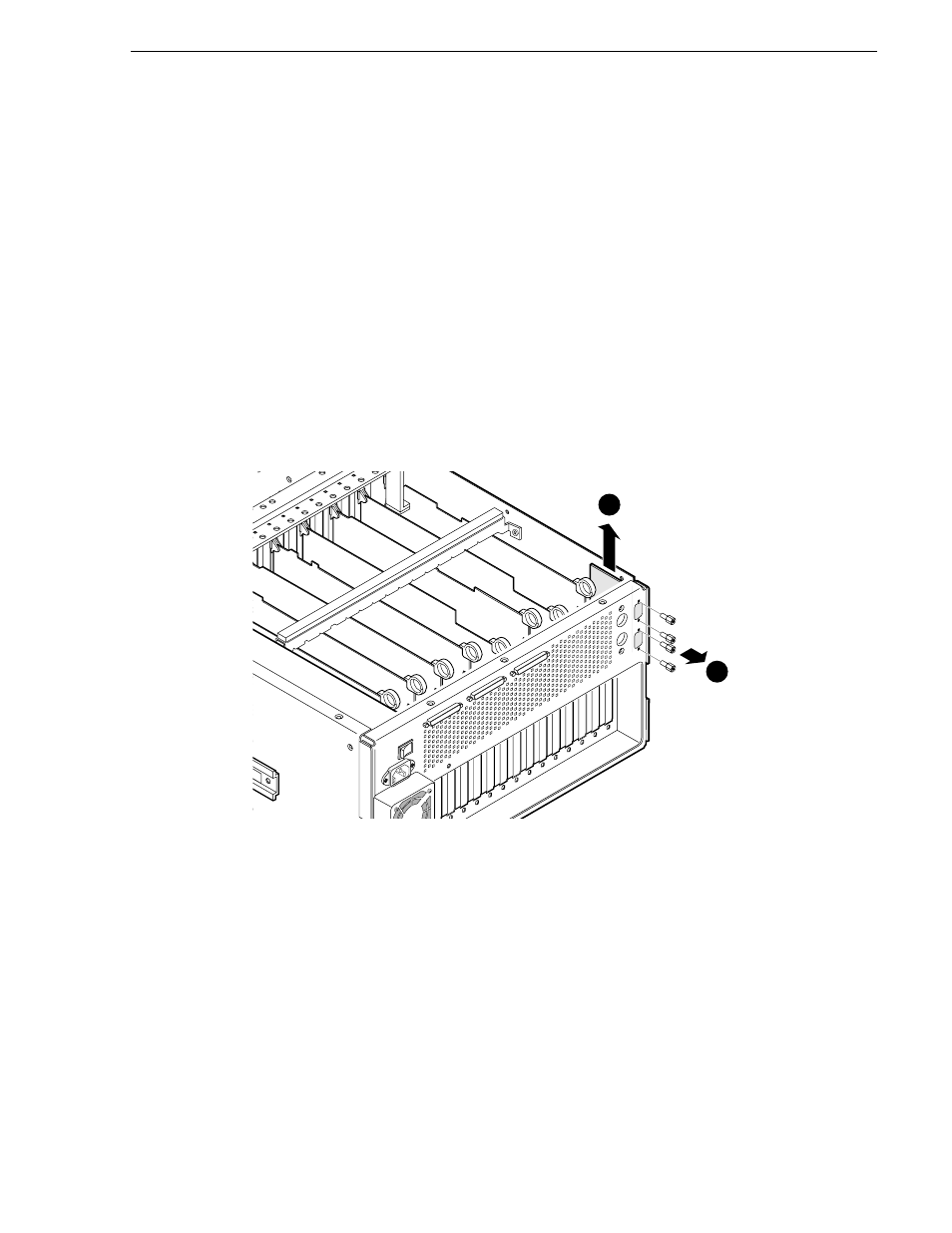
5. Use the 3/16-inch nutdriver to remove the jackscrews which secure the board to the
rear panel and lift the board up and out of the Profile chassis (1 in Figure 6-24).
6. Disconnect the cable to the Serial EMI board (2 in Figure 6-24).
Figure 6-24. Removal of the Serial EMI Board
To install the Serial EMI board:
1. Position the board in the Profile chassis so that the connectors protrude out of the rear
panel.
2. Align the screw holes and use the 3/16-inch nutdriver to secure the board to the Profile
chassis with the screws previously removed (Figure 6-24).
3. Connect the cable previously removed to the board.
4. Reinstall any boards removed (page 6-34).
5. Replace chassis covers (page 6-8) and reinstall the chassis in the rack (page 6-7).
6. Reconnect the power cord and turn PDR200 power On.
9675-16
1
2
Remove
screws(4)
Unplug cabling and
remove EMI board.